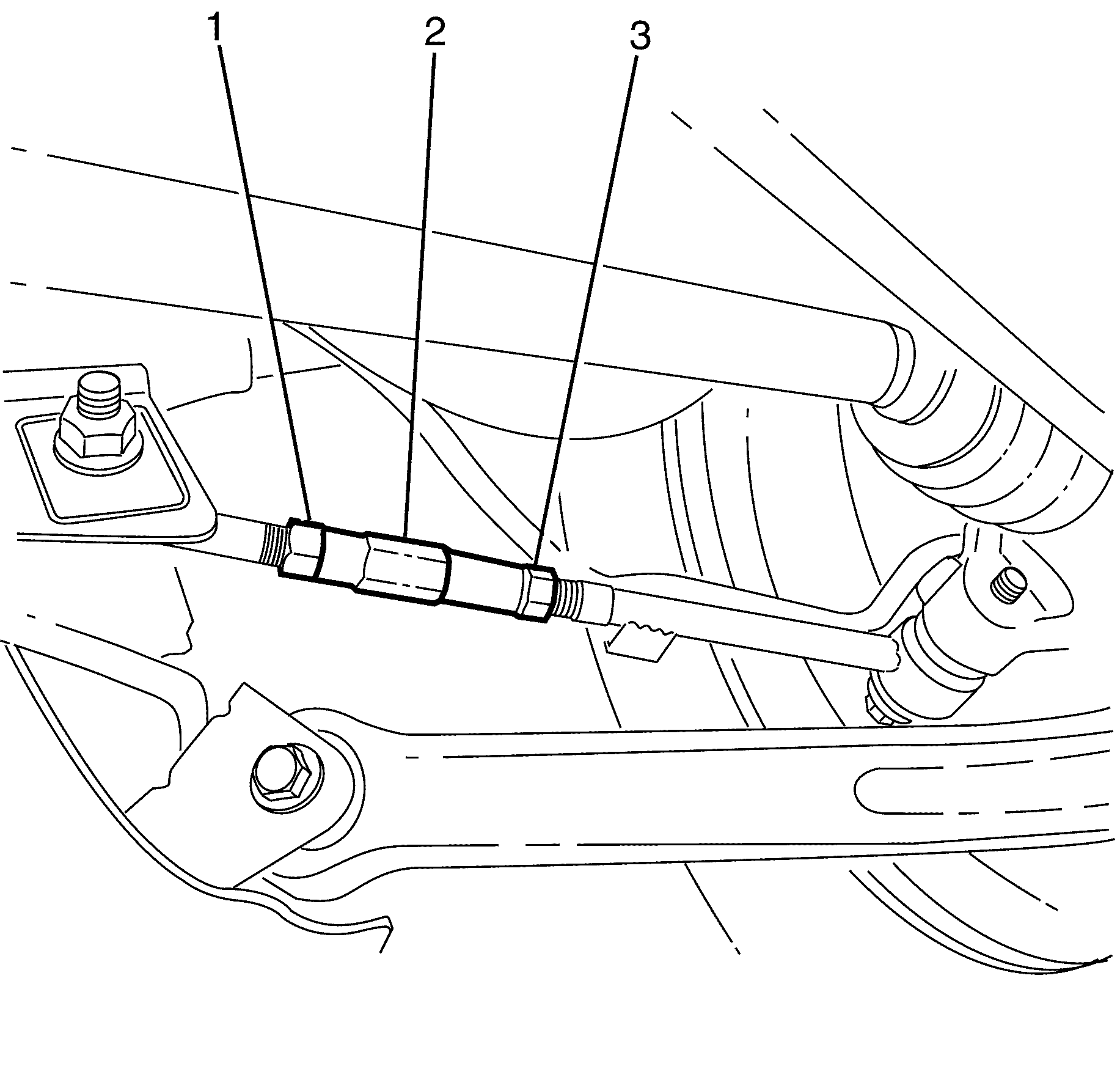
- Raise and support the vehicle. Refer to Lifting and Jacking the Vehicle.
- Loosen the I-Link adjuster lock nuts (1 and 3) from the I-Link adjuster (2).
- Remove the safety stands.
- Lower the vehicle to the ground.
- Bounce the vehicle several times to settle the suspension.
- Determine the actual rear suspension toe setting.
- Adjust the rear suspension toe to specification by turning the I-Link adjuster (2). For rear suspension toe specifications, Refer to Wheel Alignment Specifications.
- Tighten the I-Link lock nuts (1 and 3).
- Verify that the toe is still within specifications. Refer to Wheel Alignment Specifications.
- Readjust if necessary.
Warning: Refer to Safety Glasses Warning in the Preface section.
Danger: To avoid any vehicle damage, serious personal injury or death when major components are removed from the vehicle and the vehicle is supported by a hoist, support the vehicle with jack stands at the opposite end from which the components are being removed and strap the vehicle to the hoist.

Important: Before checking and adjusting any wheel alignment angles bounce the vehicle to settle the suspension to normal ride height.
Caution: Refer to Fastener Caution in the Preface section.
Important: The weight of the vehicle must be on a level surface such as an alignment rack and on all four wheels before fully tightening the bolts and nuts that have been partially tightened. Failure to comply with this requirement may adversely affect the ride and handling characteristics of the vehicle.
Important: Do not allow the I-Link adjuster (2) to turn while tightening the I-Link adjuster lock nuts (1 and 3).
Tighten
Tighten the nut to 50 N·m (37 lb ft).
