For 1990-2009 cars only
Removal Procedure
- Remove the glove box assembly. Refer to Instrument Panel Compartment Replacement.
- Remove Left side floor duct. Refer to Floor Air Outlet Duct Replacement - Left Side.
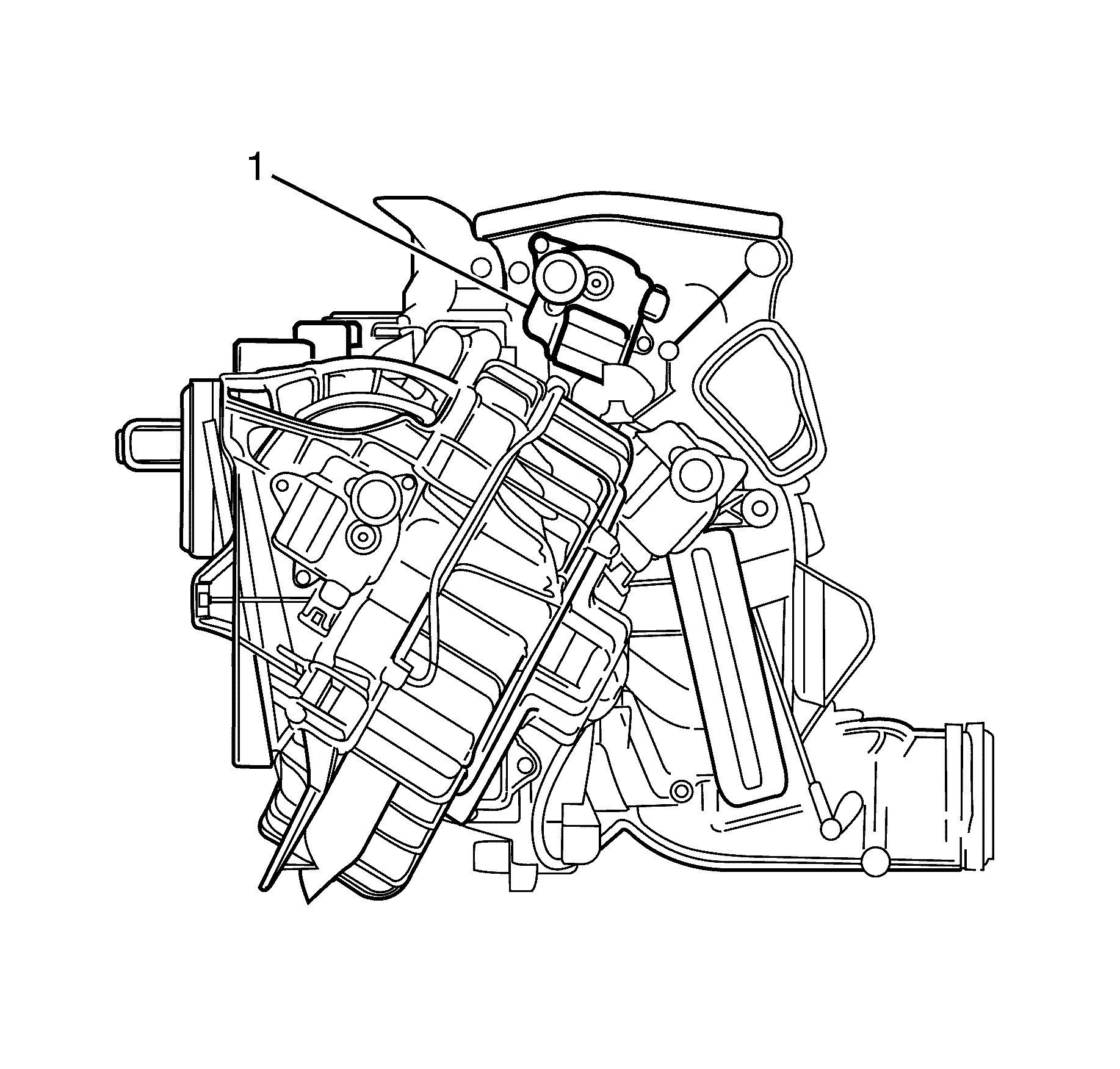
- Locate the defrost mode actuator (1) on the HVAC module assembly, passenger side.
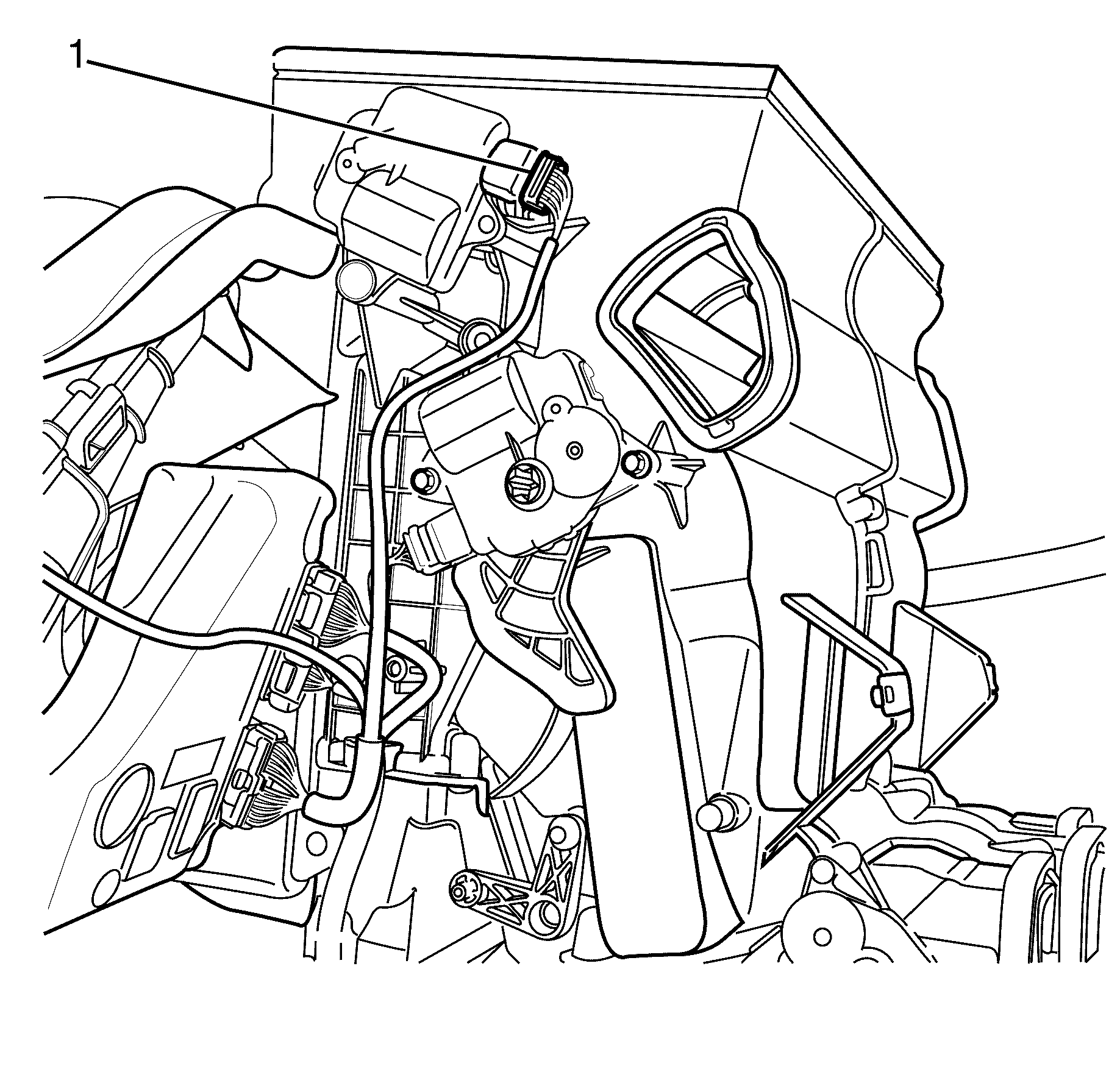
- Disconnect the electrical connector from the defrost mode actuator.
- Remove the defrost mode actuator to HVAC module assembly retaining screws.
- Remove the defrost mode actuator from the HVAC module assembly.
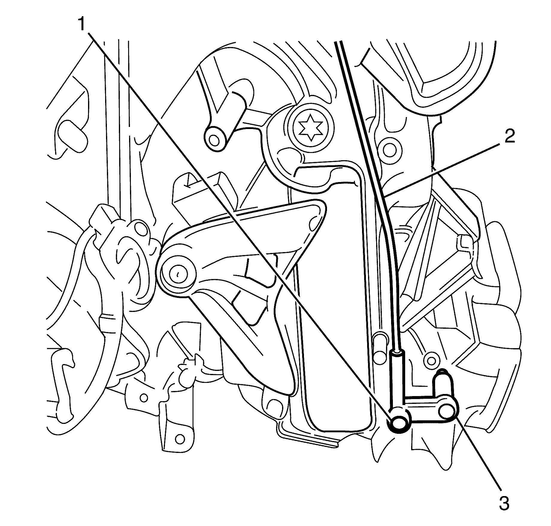
- Remove the rear passenger mode rod clip (1) from the mode door lever to assist actuator replacement.
- Remove the rear passenger mode lever as one piece from the HVAC module assembly, manoeuvring the rod through the actuator mountings.
- Detach the rear passenger mode rod from the defrost mode actuator.
- Gently remove the rear passenger mode lever from the defrost mode actuator.


Note: Squeeze the clip locators together with suitable tool.
Note: Rotate the rear passenger mode rod to match the actuator lever locking position opening, then remove rear passenger mode rod.
Note: Take note of the rear passenger mode lever position in relation to the actuator housing.
Installation Procedure
- Install the rear passenger mode lever to the defrost mode actuator.
- Attach the rear passenger mode rod to the actuator.
- Install the rear passenger mode lever as one piece, manoeuvring the rod through the actuator mountings.
- Install the rear passenger mode rod (1) clip to the mode door lever.
- Install the defrost mode actuator (1) to the HVAC.
- Install the defrost mode actuator to HVAC module assembly retaining screws and tighten to 1.5 N·m (13 lb in).
- Connect the electrical connector (1) to the defrost mode actuator.
- Install Left side floor duct. Refer to Floor Air Outlet Duct Replacement - Left Side.
- Install the glove box assembly. Refer to Instrument Panel Compartment Replacement.
- Perform HVAC system relearn.


Caution: Refer to Fastener Caution in the Preface section.

