For 1990-2009 cars only
Removal Procedure
- Remove the right side console lower extension. Refer to Instrument Panel Extension Replacement.
- Remove the instrument panel lower right trim plate assembly. Refer to Instrument Panel Insulator Panel Replacement - Right Side.
- Remove right side floor duct. Refer to Floor Air Outlet Duct Replacement - Right Side.
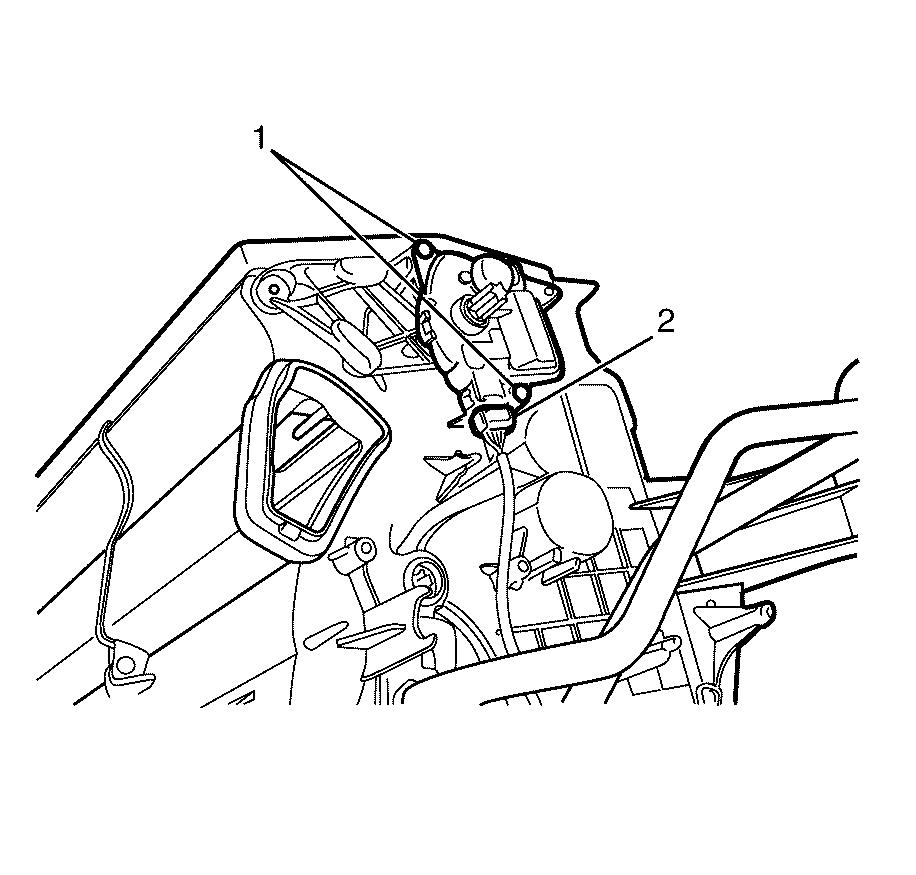
- Disconnect the face/floor actuator electrical connector (2).
- Remove the face/floor actuator to HVAC module assembly retaining screws (1).
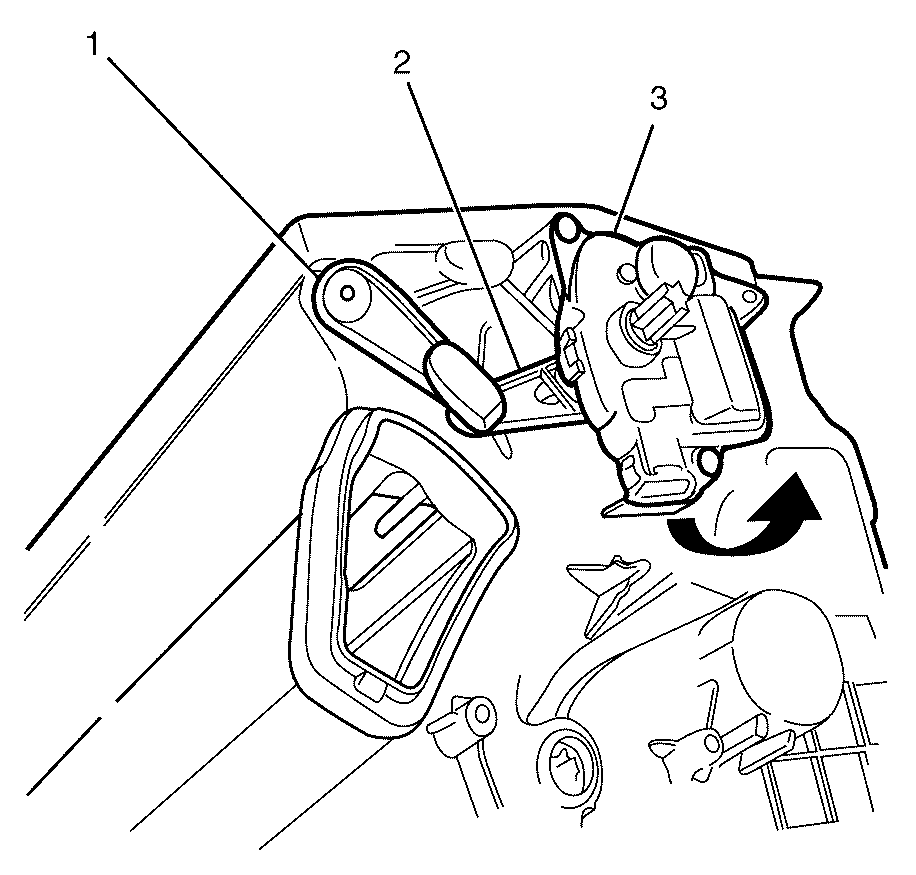
- Remove the face/floor mode actuator lever (2) from the face door mode lever (1).
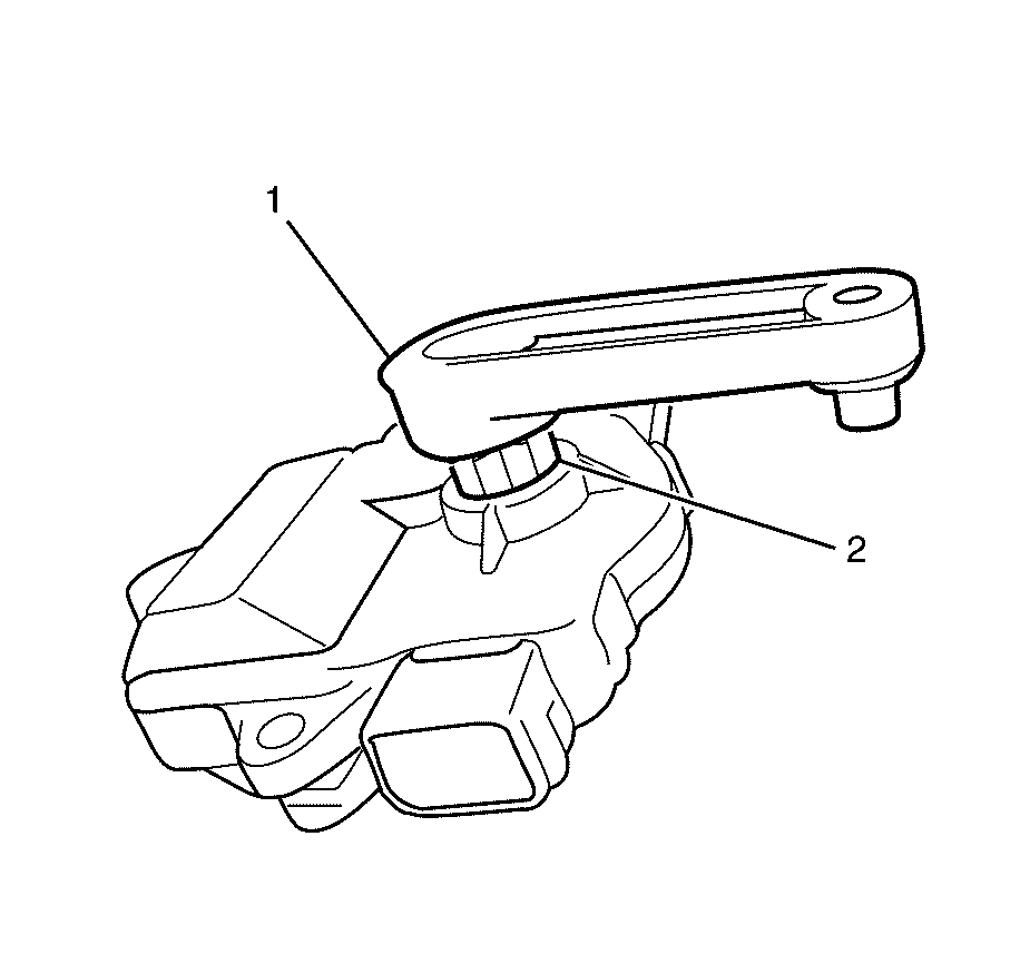
- Record where the face/floor mode actuator lever (1) is located onto the face/floor actuator drive spline (2) for installation.


Note: Pivot the face/floor mode actuator (3) upwards and remove the face/floor mode actuator lever (2) from the face door mode lever (1).

Installation Procedure
- Detach and move the face/floor mode actuator lever (1) to the recorded position on the face/floor actuator drive spline (2) as required.
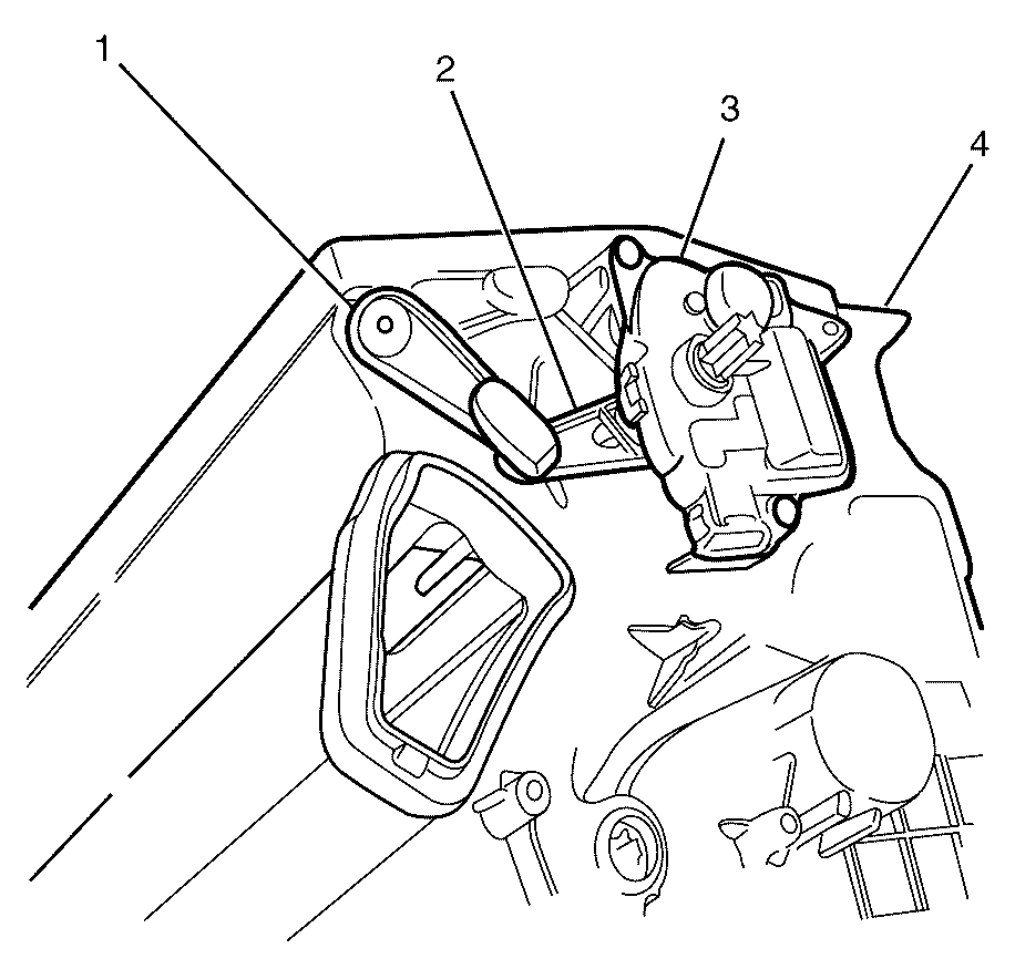
- Install the actuator lever (2) to the face door mode lever (1) and pivot the face/floor mode actuator (3) into position on the HVAC module assembly (4).
- Install the face/floor mode actuator to HVAC module assembly retaining screws (1) and tighten to 1.2 N·m (9 lb ft).
- Connect the face/floor mode actuator electrical connector (2).
- Install the instrument panel lower right trim plate assembly. Refer to Instrument Panel Insulator Panel Replacement - Right Side.
- Install right side floor duct. Refer to Floor Air Outlet Duct Replacement - Right Side.
- Perform HVAC system relearn. Refer to HVAC Control Module Programming and Setup.


Caution: Refer to Fastener Caution in the Preface section.

