Steering Gear Replacement 3.6L Engine LHD
Tools Required
Removal Procedure
- Remove the air inlet duct. Refer to Air Cleaner Inlet Duct Replacement
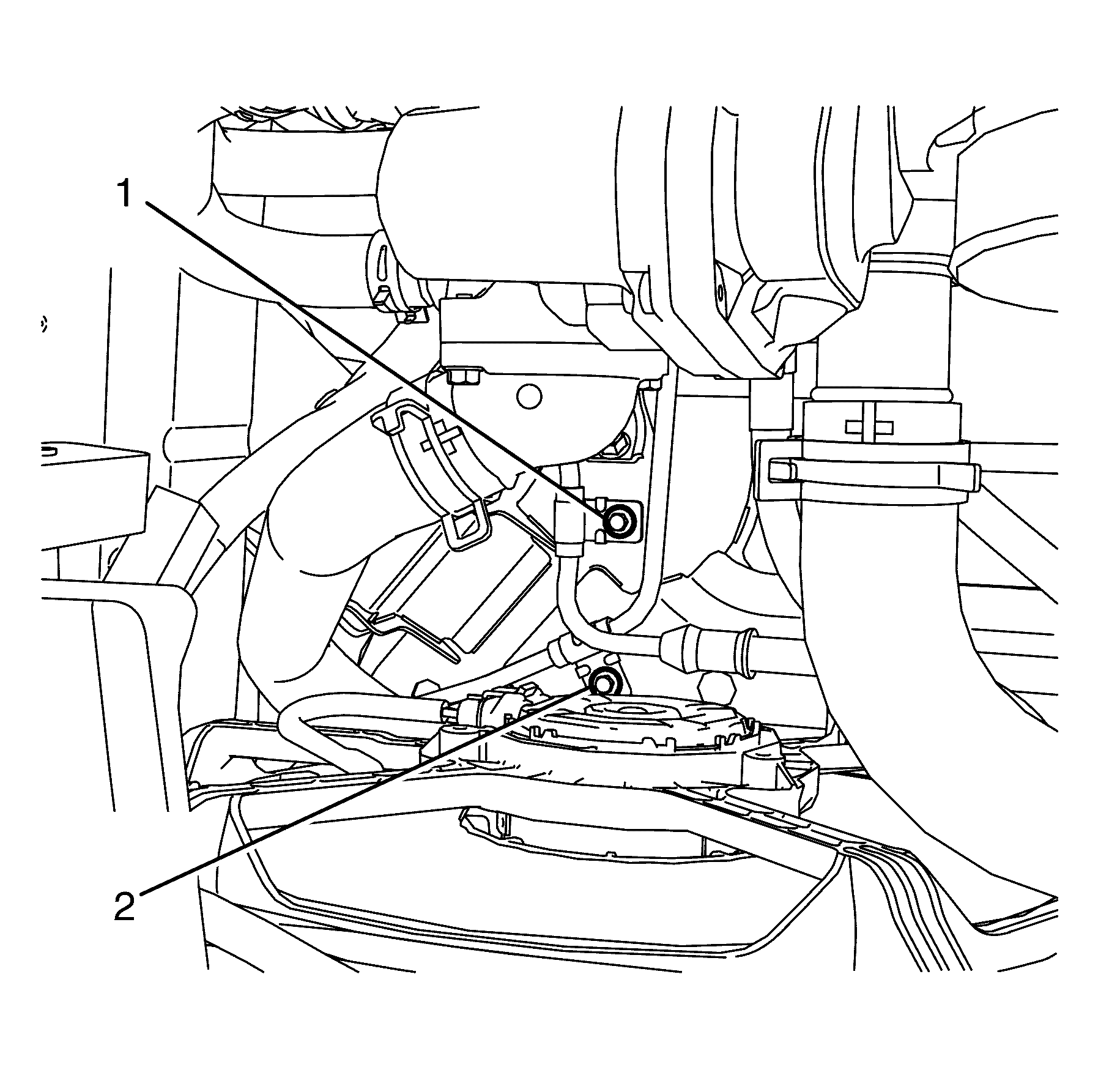
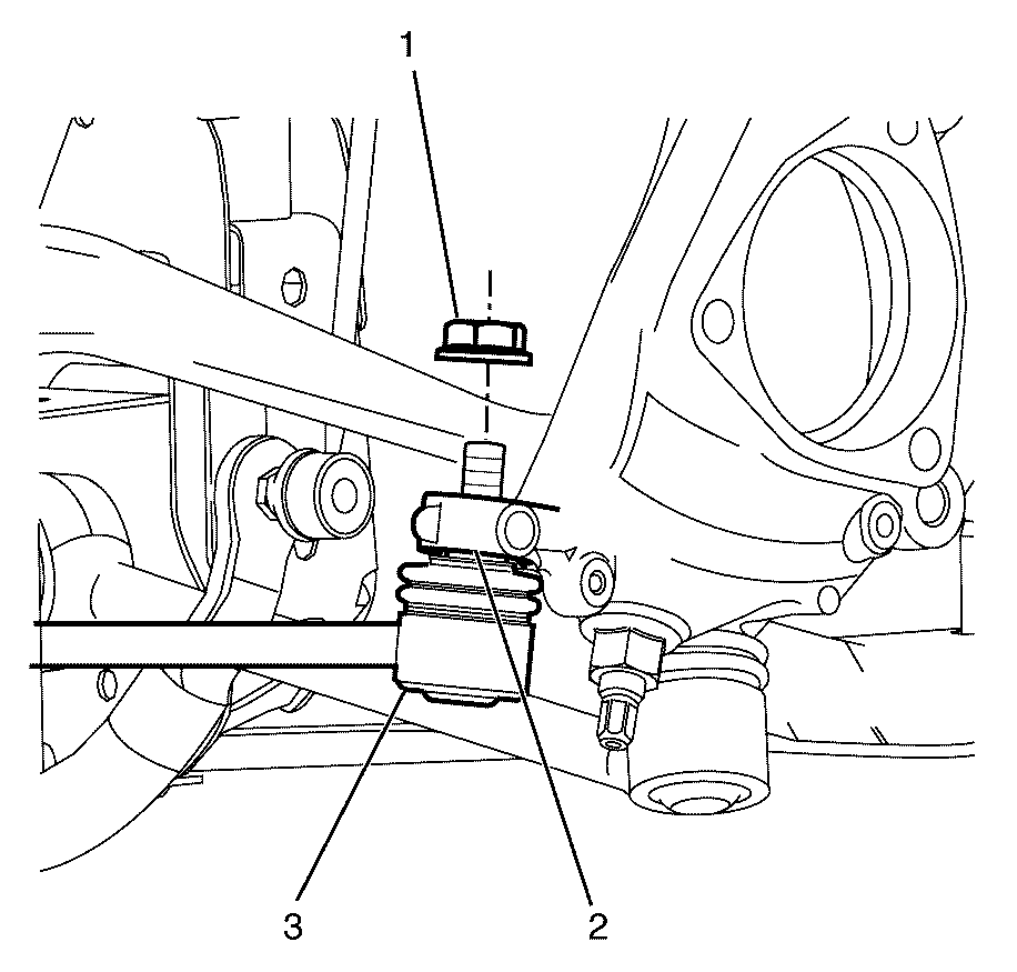
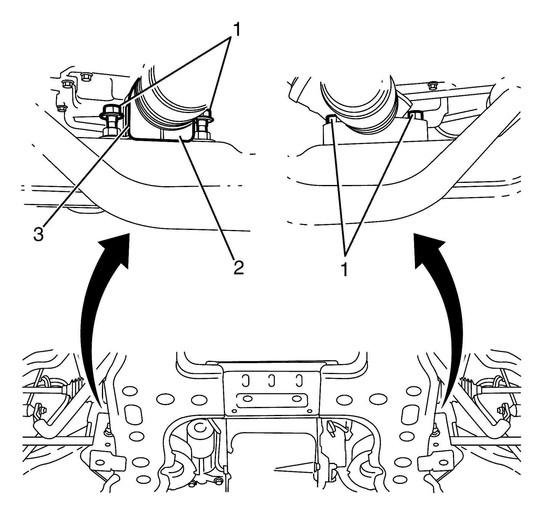
- Remove the power steering gear inlet pipe bracket to subframe retaining bolt (1).
- Remove the power steering gear outlet pipe bracket to subframe retaining bolt (2).
- Raise and support the vehicle. Refer to Lifting and Jacking the VehicleLifting and Jacking the Vehicle.
- Remove the front wheels. Refer to Tire and Wheel Removal and InstallationTire and Wheel Removal and Installation.
- Make a reference mark (5) parallel to the tie rod end lock nut (2) and the tie rod end (3).
- Measure and make a note of the distance of the thread (A) in relation to the tie rod end lock nut (2).
- Loosen the tie rod end lock nut (2) half a turn.
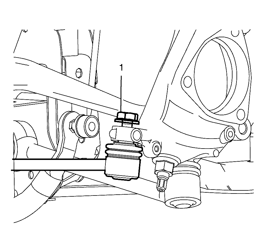
- Loosen the tie rod end to steering knuckle retaining nut (1) about two turns.
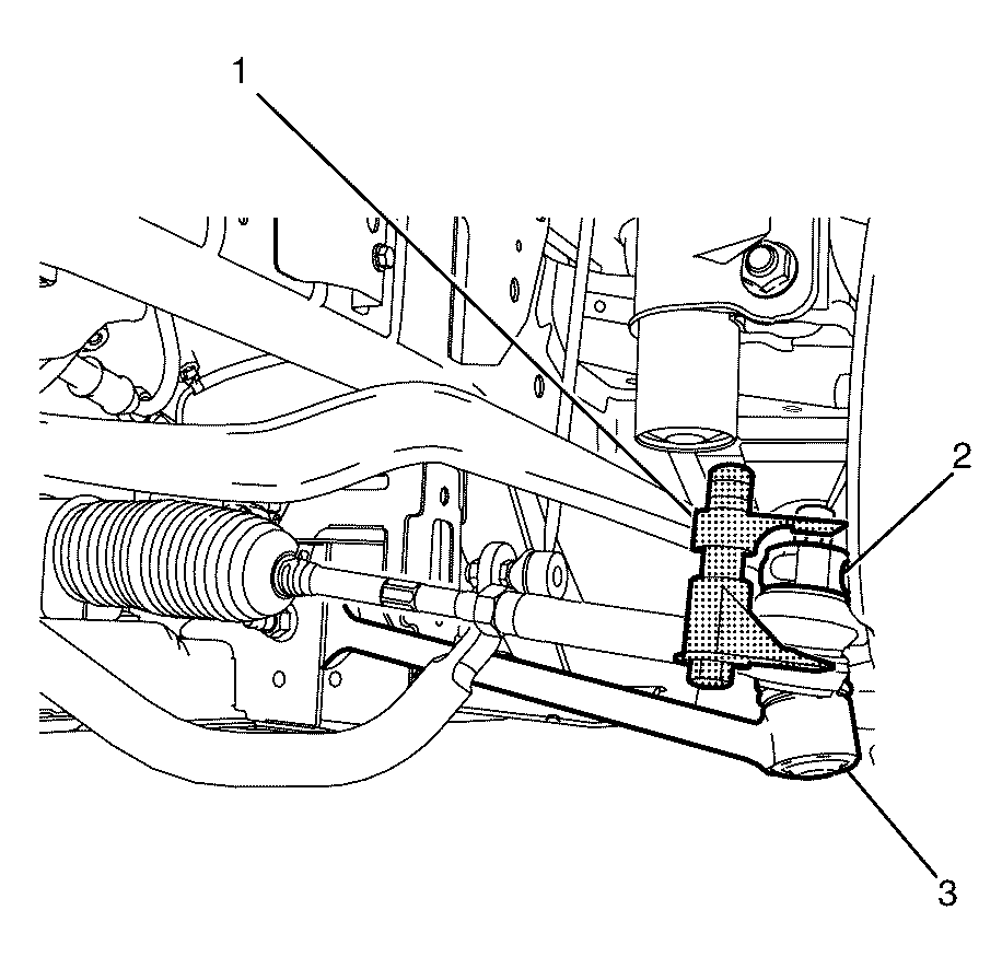
- Using J-42188-B (1) disconnect the tie rod end (3) from the steering knuckle (2).
- Remove and discard the tie rod end to steering knuckle retaining nut (1).
- Separate the tie rod end (3) from the steering knuckle (2).
- Repeat steps 7 to 11 on the opposite side of the vehicle.
- Remove the engine splash shield. Refer to Engine Splash Shield ReplacementEngine Splash Shield Replacement.
- Make a reference mark (3) parallel to the intermediate steering shaft (1) and the pinion shaft (4).
- Remove and discard the intermediate steering shaft to pinion shaft retaining bolt (2).
- Disconnect the intermediate shaft (1) from the pinion shaft (4).
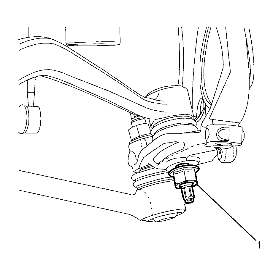
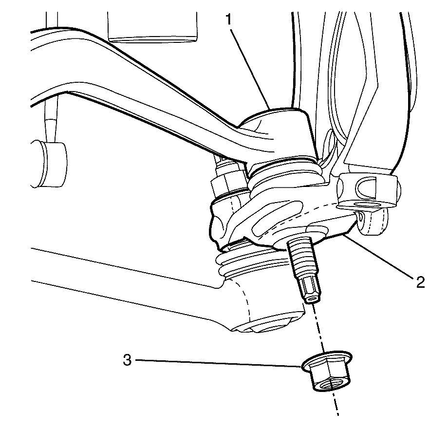
- Loosen the caster arm to steering knuckle retaining nut (1) about two turns.
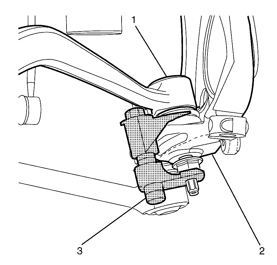
- Using J-42188-B (1) disconnect the driver side caster arm (1) from the steering knuckle (2).
- Remove and discard the driver side caster arm to steering knuckle retaining nut (3).
- Separate the driver side caster arm (1) from the steering knuckle (2).
- Place a suitable container under the vehicle below the power steering gear inlet pipe to power steering gear retaining banjo bolt (2) and the power steering gear outlet pipe to power steering gear retaining banjo bolt (3) to collect draining fluid.
- Remove the power steering gear inlet pipe to power steering gear retaining banjo bolt (2).
- Remove and discard the copper sealing washers (1).
- Plug the steering gear inlet pipe (6) to prevent the entry of foreign particles into the power steering system.
- Remove the power steering gear outlet pipe to power steering gear retaining banjo bolt (3).
- Remove and discard the copper sealing washers (4).
- Plug the steering gear outlet pipe (5) to prevent the entry of foreign particles into the power steering system.
- Remove the and discard the steering gear to subframe retaining bolts (1).
- Remove the steering gear insulator retaining bracket (2) from the steering gear insulator (3).
- Remove the steering gear insulator (3) from the steering gear.
- Remove the steering gear assembly from the vehicle.
Warning: Refer to Safety Glasses Warning in the Preface section.
Danger: To avoid any vehicle damage, serious personal injury or death when major components are removed from the vehicle and the vehicle is supported by a hoist, support the vehicle with jack stands at the opposite end from which the components are being removed and strap the vehicle to the hoist.
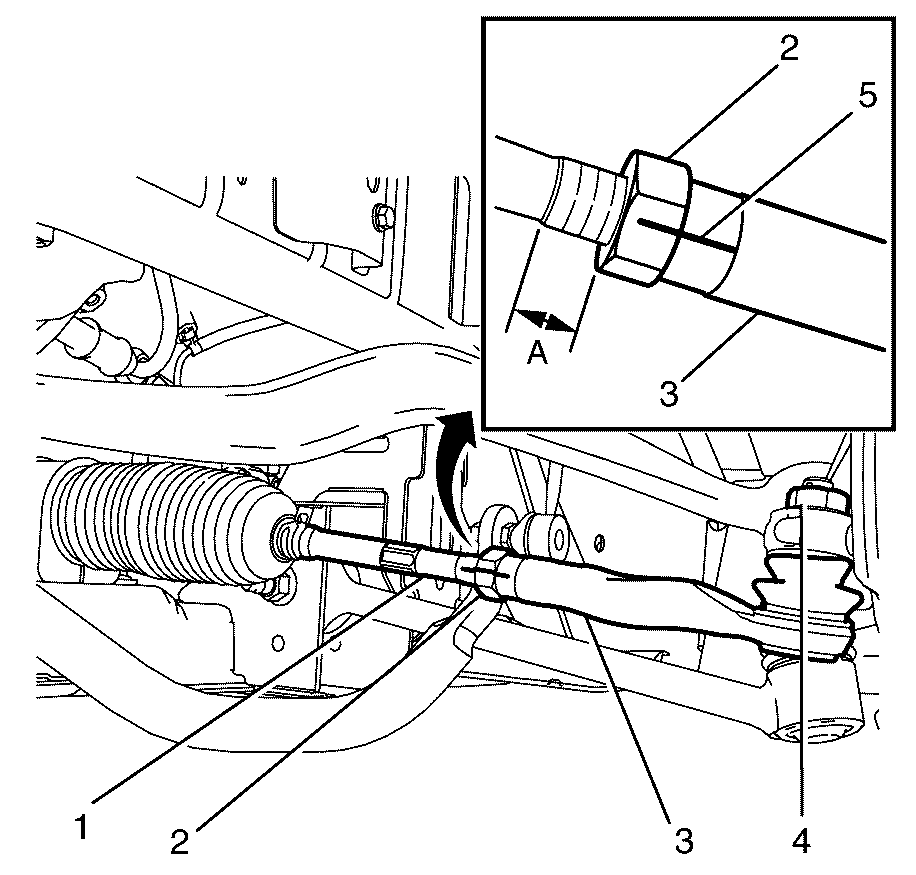
Note: Make reference markings on the tie rod end lock nut (2) and the tie rod end (3) before loosening the tie rod end lock nut (2).
Note: Measure the distance of the thread (A) in relation to the tie rod end lock nut (2) before loosening the tie rod end lock nut (2).
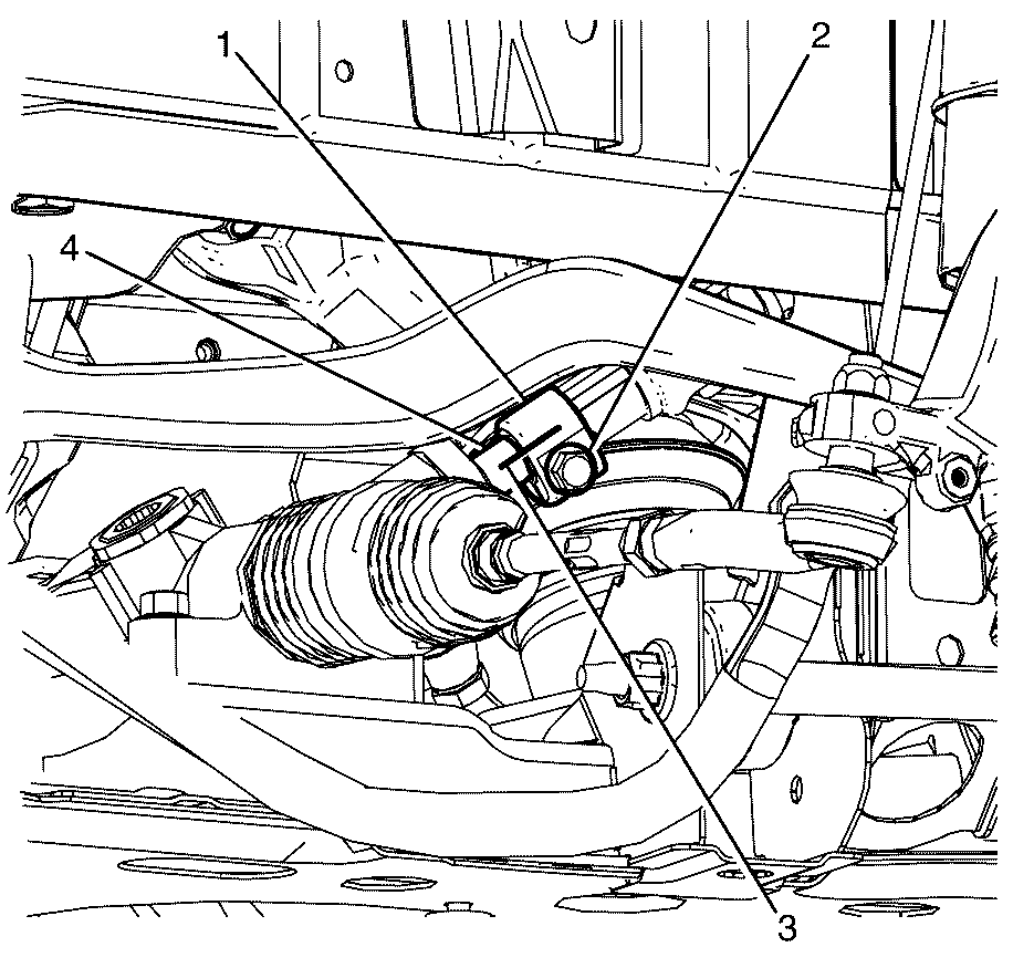
Note: Observing the orientation of the intermediate steering shaft (1) with reference to the pinion shaft (4) will assist in steering alignment.

Note: The steering gear assembly must be removed from the driver side of the vehicle.
Installation Procedure
- Install the steering gear to the vehicle.
- Install the steering gear insulator (3) to the steering gear.
- Install the steering gear insulator retaining bracket (2) to the steering gear insulator (3).
- Install the steering gear to subframe retaining bolts (1) and tighten to 65 N·m (48 lb ft).
- Remove the plug from the steering gear outlet pipe (5).
- Install the NEW copper sealing washers (4).
- Install the power steering gear outlet pipe to power steering gear retaining banjo bolt (3) and tighten to 58 N·m (43 lb ft).
- Remove the plug from the steering gear inlet pipe (6).
- Install the NEW copper sealing washers (1).
- Install the power steering gear inlet pipe to power steering gear retaining banjo bolt (2) and tighten to 58 N·m (43 lb ft).
- Remove the container with the drained fluid from the vehicle.
- Install the driver side caster arm (1) to the steering knuckle (2).
- Install the driver side front castor arm ball joint to steering knuckle NEW retaining nut (3).
- Align the reference mark (3) on the intermediate steering shaft (1) and the reference mark (3) on the pinion shaft (4).
- Connect the intermediate steering shaft (1) to the pinion shaft (4).
- Install the NEW intermediate steering shaft to pinion shaft retaining bolt (2) and tighten to 25 N·m (18 lb ft).
- Connect the tie rod end (3) to the steering gear assembly (1)
- Connect the tie rod end (3) to the steering knuckle (4).
- Install the NEW tie rod end to steering knuckle retaining nut (5) and tighten to 70 N·m (52 lb ft).
- Repeat steps 17 to 19 on the opposite side of the vehicle.
- Install the engine splash shield. Refer to Engine Splash Shield ReplacementEngine Splash Shield Replacement.
- Install the front wheels. Refer to Tire and Wheel Removal and InstallationTire and Wheel Removal and Installation.
- Lower the vehicle.
- Install the power steering gear inlet pipe bracket to subframe retaining bolt (1) and tighten to 9 N·m (80 lb in).
- Install the power steering gear outlet pipe bracket to subframe retaining bolt (2) and tighten to 9 N·m (80 lb in).
- Fill the power steering fluid reservoir to the MAXIMUM level marking.
- Bleed the power steering system. Refer to Power Steering System Bleeding.
- Check for power steering fluid leaks.
- Install the air inlet duct. Refer to Air Cleaner Inlet Duct Replacement.
- Install the front wheels. Refer to Tire and Wheel Removal and InstallationTire and Wheel Removal and Installation.
- Lower the vehicle.
- Bounce the vehicle several times to settle the suspension.
- Check and adjust the wheel alignment. Refer to Wheel Alignment Measurementin Wheel Alignment.
- Tighten the tie rod end lock nut (1) and tighten to 50 N·m (37 lb ft).

Note: The steering gear must be installed from the driver side of the vehicle.
Caution: Refer to Fastener Caution in the Preface section.


Install the NEW driver side caster arm to steering knuckle retaining nut (3).
Tighten
| • | First Pass: Tighten the nut to 40 N·m (30 lb ft). |
| • | Final Pass: Tighten the nut an additional 60 degrees using E7115 . |

Note: Aligning the reference marks (3) will minimise the steering adjustment procedure.
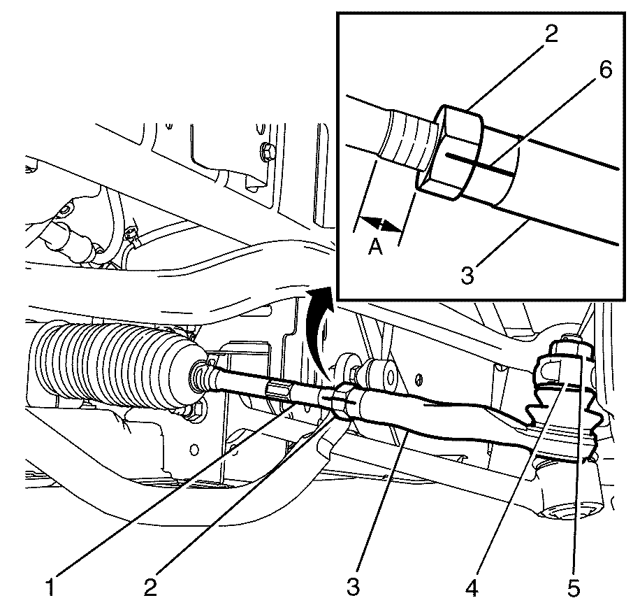
Note: To minimise the wheel alignment procedure the tie rod end (3) must be installed the distance (A) as was noted in the removal procedure.
Note: To minimise the wheel alignment procedure align the reference mark (5) on the tie rod end (3) and the reference mark (5) on the tie rod end lock nut (2).
Note: The tie rod end lock nut (2) is not to be fully tightened at this stage.

Notice: When adding fluid or making a complete fluid change, always use the proper power steering fluid. Failure to use the proper fluid will cause hose and seal damage and fluid leaks.

Steering Gear Replacement 6.0L Engine
Special Tools
Removal Procedure
- Remove the engine cover. Refer to Engine Cover Replacement.
- Remove the air inlet duct. Refer to Air Cleaner Inlet Duct Replacement.
- Remove the power steering gear inlet pipe bracket to subframe retaining bolt (1).
- Remove the power steering gear outlet pipe bracket to subframe retaining bolt (2).
- Raise and support the vehicle. Refer to Lifting and Jacking the Vehicle.
- Remove the front wheels. Refer to Tire and Wheel Removal and Installation.
- Make a reference mark (5) parallel to the tie rod end lock nut (2) and the tie rod end (3).
- Measure and make a note of the distance of the thread (A) in relation to the tie rod end lock nut (2).
- Loosen the tie rod end lock nut (2) half a turn.
- Loosen the tie rod end to steering knuckle retaining nut (1) about two turns.
- Using J-42188-B (1) disconnect the tie rod end (3) from the steering knuckle (2).
- Remove and discard the tie rod end to steering knuckle retaining nut (1).
- Separate the tie rod end (3) from the steering knuckle (2).
- Repeat steps 7 to 13 on the opposite side of the vehicle.
- Remove the engine splash shield. Refer to Engine Splash Shield ReplacementEngine Splash Shield Replacement.
- Make a reference mark (3) parallel to the intermediate steering shaft (1) and the pinion shaft (4).
- Remove and discard the intermediate steering shaft to pinion shaft retaining bolt (2).
- Disconnect the intermediate shaft (1) from the pinion shaft (4).
- Loosen the caster arm to steering knuckle retaining nut (1) about two turns.
- Using J-42188-B (1) disconnect the driver side caster arm (1) from the steering knuckle (2).
- Remove and discard the driver side caster arm to steering knuckle retaining nut (3).
- Separate the driver side caster arm (1) from the steering knuckle (2).
- Place a suitable container under the vehicle below the power steering gear inlet pipe to power steering gear retaining banjo bolt (2) and the power steering gear outlet pipe to power steering gear retaining banjo bolt (3) to collect draining fluid.
- Remove the power steering gear inlet pipe to power steering gear retaining banjo bolt (2).
- Remove and discard the copper sealing washers (1).
- Plug the steering gear inlet pipe (6) to prevent the entry of foreign particles into the power steering system.
- Remove the power steering gear outlet pipe to power steering gear retaining banjo bolt (3).
- Remove and discard the copper sealing washers (4).
- Plug the steering gear outlet pipe (5) to prevent the entry of foreign particles into the power steering system.
- Remove the and discard the steering gear to subframe retaining bolts (1).
- Remove the steering gear insulator retaining bracket (2) from the steering gear insulator (3).
- Remove the steering gear insulator (3) from the steering gear.
- Remove the steering gear assembly from the vehicle.
Warning: Refer to Safety Glasses Warning in the Preface section.
Danger: To avoid any vehicle damage, serious personal injury or death when major components are removed from the vehicle and the vehicle is supported by a hoist, support the vehicle with jack stands at the opposite end from which the components are being removed and strap the vehicle to the hoist.


Note: Make reference markings on the tie rod end lock nut (2) and the tie rod end (3) before loosening the tie rod end lock nut (2).
Note: Measure the distance of the thread (A) in relation to the tie rod end lock nut (2) before loosening the tie rod end lock nut (2).


Note: Observing the orientation of the intermediate steering shaft (1) with reference to the pinion shaft (4) will assist in steering alignment.


Note: The steering gear assembly must be removed from the driver side of the vehicle.
Installation Procedure
- Install the steering gear to the vehicle.
- Install the steering gear insulator (3) to the steering gear.
- Install the steering gear insulator retaining bracket (2) to the steering gear insulator (3).
- Install the steering gear to subframe retaining bolts (1) and tighten to 65 N·m (48 lb ft).
- Remove the plug from the steering gear outlet pipe (5).
- Install the NEW copper sealing washers (4).
- Install the power steering gear outlet pipe to power steering gear retaining banjo bolt (3) and tighten to 58 N·m (43 lb ft).
- Remove the plug from the steering gear inlet pipe (6).
- Install the NEW copper sealing washers (1).
- Install the power steering gear inlet pipe to power steering gear retaining banjo bolt (2) and tighten to 58 N·m (43 lb ft).
- Remove the container with the drained fluid from the vehicle.
- Install the driver side caster arm (1) to the steering knuckle (2).
- Install the driver side front castor arm ball joint to steering knuckle NEW retaining nut (3).
- Align the reference mark (3) on the intermediate steering shaft (1) and the reference mark (3) on the pinion shaft (4).
- Connect the intermediate steering shaft (1) to the pinion shaft (4).
- Install the NEW intermediate steering shaft to pinion shaft retaining bolt (2) and tighten to 25 N·m (18 lb ft).
- Connect the tie rod end (3) to the steering gear assembly (1)
- Connect the tie rod end (3) to the steering knuckle (4).
- Install the NEW tie rod end to steering knuckle retaining nut (5) and tighten to 70 N·m (52 lb ft).
- Repeat steps 17 to 19 on the opposite side of the vehicle.
- Install the engine splash shield. Refer to Engine Splash Shield ReplacementEngine Splash Shield Replacement.
- Install the front wheels. Refer to Tire and Wheel Removal and InstallationTire and Wheel Removal and Installation.
- Lower the vehicle.
- Install the power steering gear inlet pipe bracket to subframe retaining bolt (1) and tighten to 9 N·m (80 lb in).
- Install the power steering gear outlet pipe bracket to subframe retaining bolt (2) and tighten to 9 N·m (80 lb in).
- Fill the power steering fluid reservoir to the MAXIMUM level marking.
- Bleed the power steering system. Refer to Power Steering System Bleeding.
- Check for power steering fluid leaks.
- Install the air inlet duct. Refer to Air Cleaner Inlet Duct Replacement.
- Install the front wheels. Refer to Tire and Wheel Removal and InstallationTire and Wheel Removal and Installation.
- Lower the vehicle.
- Bounce the vehicle several times to settle the suspension.
- Check and adjust the wheel alignment. Refer to Wheel Alignment Measurementin Wheel Alignment.
- Tighten the tie rod end lock nut (1) and tighten to 50 N·m (37 lb ft).

Note: The steering gear must be installed from the driver side of the vehicle.
Caution: Refer to Fastener Caution in the Preface section.


Install the NEW driver side caster arm to steering knuckle retaining nut (3).
Tighten
| • | First Pass: Tighten the nut to 40 N·m (30 lb ft). |
| • | Final Pass: Tighten the nut an additional 60 degrees using E7115 . |

Note: Aligning the reference marks (3) will minimise the steering adjustment procedure.

Note: To minimise the wheel alignment procedure the tie rod end (3) must be installed the distance (A) as was noted in the removal procedure.
Note: To minimise the wheel alignment procedure align the reference mark (5) on the tie rod end (3) and the reference mark (5) on the tie rod end lock nut (2).
Note: The tie rod end lock nut (2) is not to be fully tightened at this stage.

Notice: When adding fluid or making a complete fluid change, always use the proper power steering fluid. Failure to use the proper fluid will cause hose and seal damage and fluid leaks.

