For 1990-2009 cars only
Removal Procedure
- Raise and support the vehicle. Refer to Lifting and Jacking the Vehicle.
- Remove the front wheel. Refer to Tire and Wheel Removal and Installation.
- Remove the front wheel hub assembly. Refer to Front Wheel Bearing and Hub Replacement.
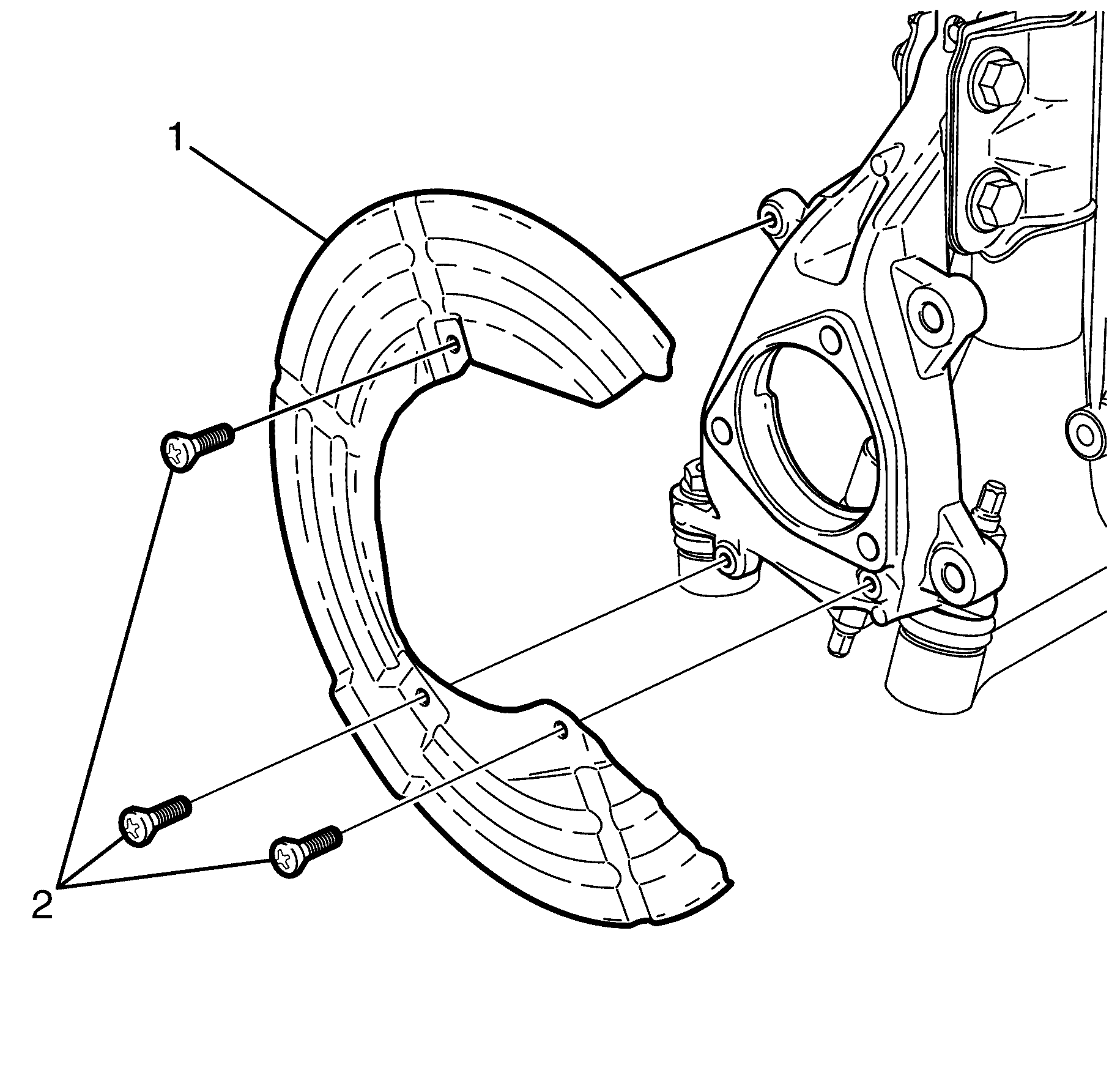
- Remove the brake disc splash shield to steering knuckle retaining bolts (2).
- Remove the brake disc splash shield (1).
Warning: Refer to Safety Glasses Warning in the Preface section.
Danger: To avoid any vehicle damage, serious personal injury or death when major components are removed from the vehicle and the vehicle is supported by a hoist, support the vehicle with jack stands at the opposite end from which the components are being removed and strap the vehicle to the hoist.
Installation Procedure
- Install the brake disc splash shield (1).
- Install the brake disc splash shield to steering knuckle retaining bolts (2) and tighten to 9 N·m (89 lb in).
- Install the front wheel hub assembly. Refer to Front Wheel Bearing and Hub Replacement.
- Install the front wheel. Refer to Lifting and Jacking the Vehicle.
- Remove the safety stands.
- Lower the vehicle to the ground.
- Bounce the vehicle several times to settle the suspension.
- Inspect and adjust the wheel alignment. Refer to Wheel Alignment Measurement.
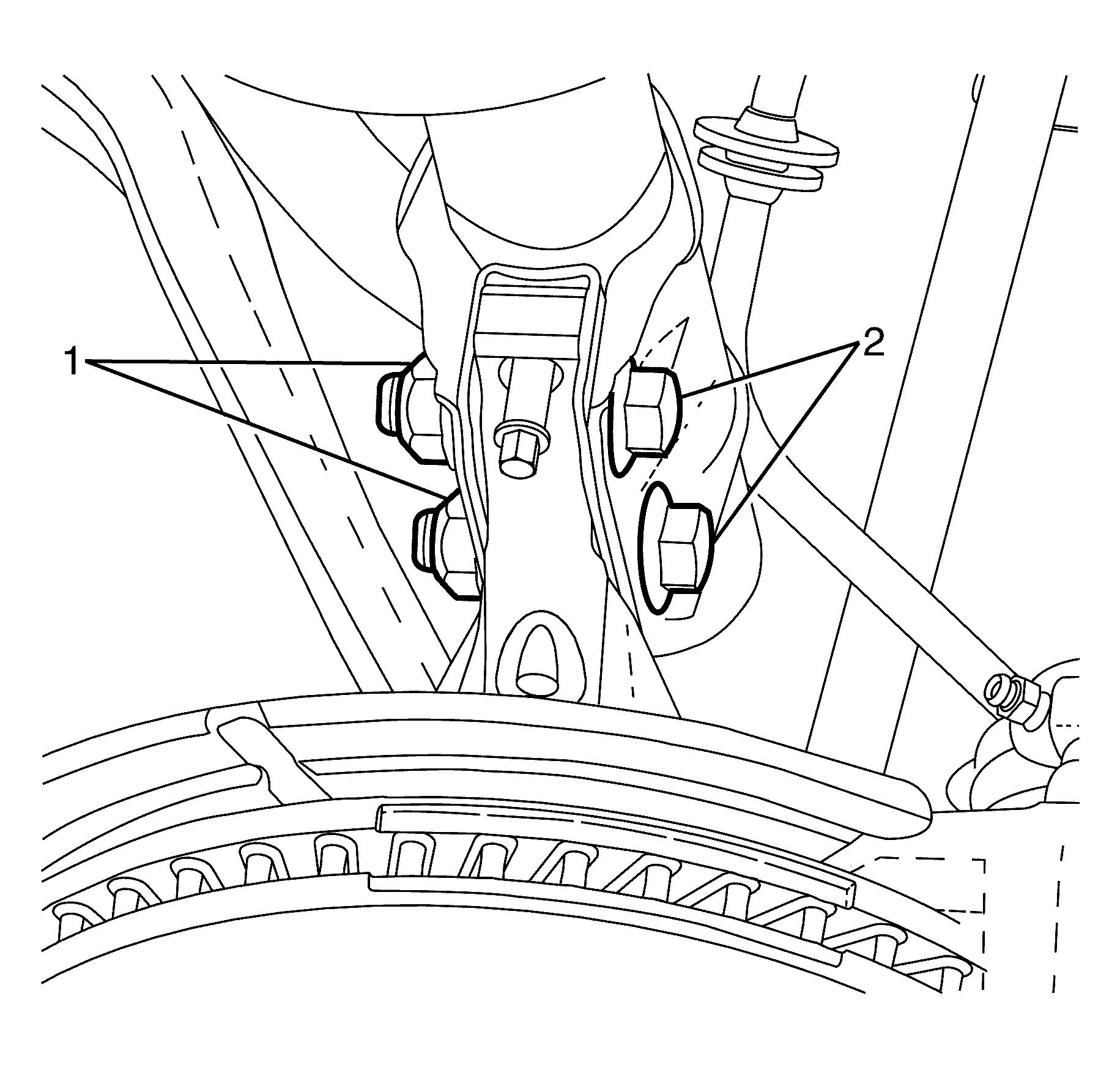
- Tighten the strut assembly to steering knuckle retaining bolts (2) and nuts (1). Tighten the bolts a first pass to 85 N·m (63 lb in). Tighten the bolts a second pass to 100 N·m (74 lb in). Tighten the bolts an additional 90 degrees.
Caution: Refer to Fastener Caution in the Preface section.
Note: If the steering knuckle has been replaced, the end-float measurement must be inspected.
