Special Tools
KM-619 Bushing Remover/Installer.
Removal Procedure
- Raise and support the vehicle. Refer to Lifting and Jacking the Vehicle.
- Remove the subframe. Refer to Rear Frame Replacement.
- Remove the upper control arm pivot bushing. Refer to Control Arm Bushing Replacement
- Remove the upper control arm. Refer to Upper Control Arm Replacement.
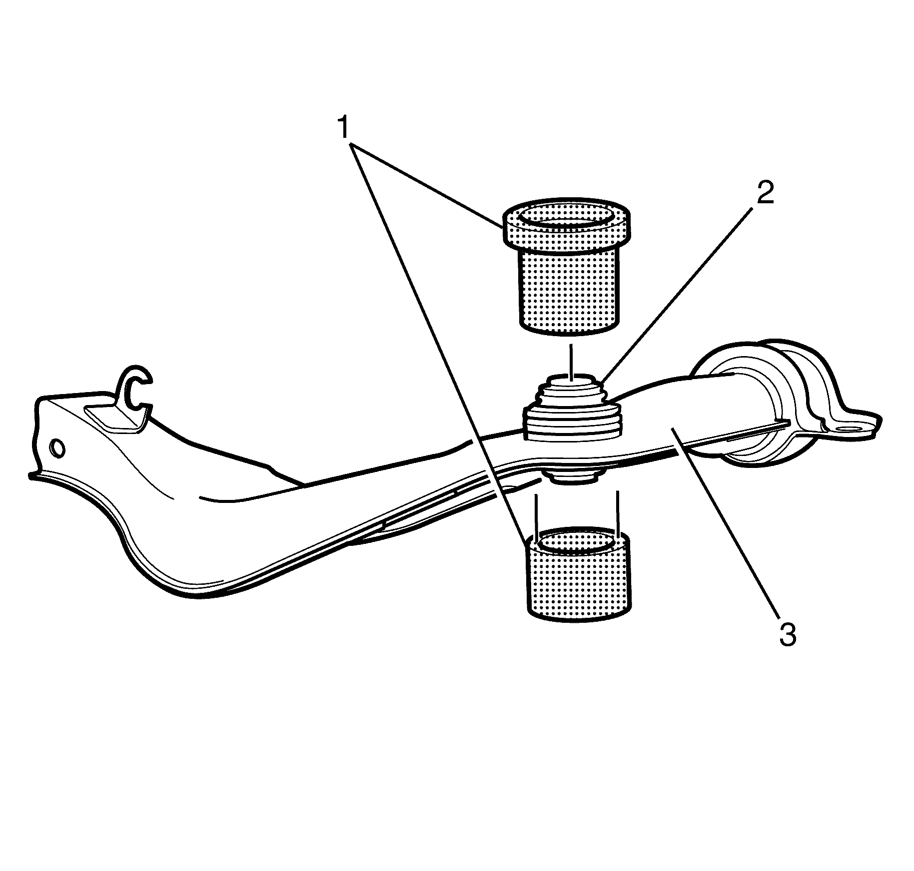
- Remove the upper control arm ball joint bushing (2) from the upper control arm (3) using the KM-619 (1).
- Inspect all parts for wear and damage.
Warning: Refer to Safety Glasses Warning in the Preface section.
Danger: To avoid any vehicle damage, serious personal injury or death when major components are removed from the vehicle and the vehicle is supported by a hoist, support the vehicle with jack stands at the opposite end from which the components are being removed and strap the vehicle to the hoist.

Note: It is recommended to observe the orientation and depth of the upper control arm ball joint bushing (2) with reference to the original position. Adhering to this recommendation will minimize the potential of incorrect upper control arm ball joint bushing (2) installation.
Installation Procedure
- Install the upper control arm ball joint bushing (2) using the KM-619 (1).
- Install the upper control arm (3). Refer to Upper Control Arm Replacement.
- Install the upper control arm pivot bushing. Refer to Control Arm Bushing Replacement.
- Install the subframe. Refer to Rear Frame Replacement.
- Remove the safety stands.
- Lower the vehicle to the ground.
- Check the vehicle rear wheel alignment and adjust if necessary. Refer to Wheel Alignment Measurement.

Note: Before installing, the upper control arm ball joint bushing (2) must be correctly aligned and orientated. The depth to which the bushing is going to travel must also be observed and maintained.
