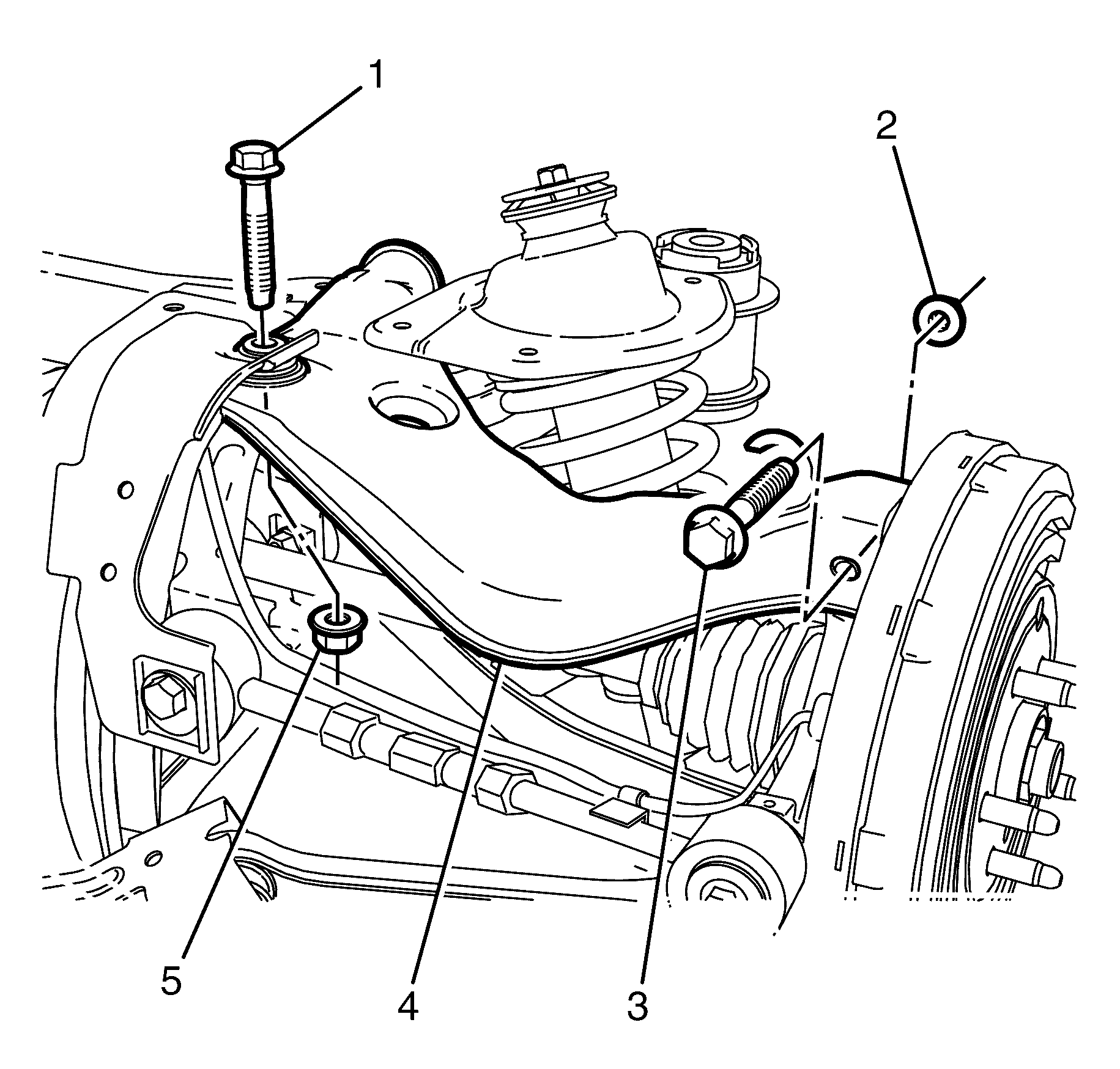
For 1990-2009 cars only
Removal Procedure
- Raise and support the vehicle. Refer to Lifting and Jacking the Vehicle.
- Remove the subframe. Refer to Rear Frame Replacement.
- Remove the upper control arm pivot bushing. Refer to Control Arm Bushing Replacement.
- Remove the upper control arm ball joint bushing to subframe retaining bolt (1) and nut (5).
- Remove the upper control arm to knuckle retaining bolt (3) and nut (2).
- Remove the upper control arm (4).
- Inspect all parts for wear and damage.
Warning: Refer to Safety Glasses Warning in the Preface section.
Danger: To avoid any vehicle damage, serious personal injury or death when major components are removed from the vehicle and the vehicle is supported by a hoist, support the vehicle with jack stands at the opposite end from which the components are being removed and strap the vehicle to the hoist.

Note: Mark the location of the bolt and nut relative to the Y-Link for correct re-assembly.
Note: Prevailing torque nuts must be replaced after removal.
Discard the nut.
Discard the nut.
Installation Procedure
- Install the upper control arm (4) into the subframe.
- Install the upper control arm ball joint bushing to subframe retaining bolt (1) and NEW nut (5) and tighten.
- Install the upper control arm to knuckle retaining bolt (3) and NEW nut (2) and tighten.
- Install the upper control arm pivot bushing. Refer Control Arm Bushing Replacement.
- Install the subframe. Refer to Rear Frame Replacement.
- Remove the safety stands.
- Lower the vehicle to the ground.
- Check the vehicle rear wheel alignment and adjust if necessary. Refer to Wheel Alignment Specifications.
Caution: Refer to Fastener Caution in the Preface section.

| • | the bolt and nut a first pass to 80 N·m (59 lb ft) |
| • | the bolt and nut a final pass 120 Degrees. |
| • | the bolt and nut a first pass to 60 N·m (44 lb ft) |
| • | the bolt and nut a final pass 90 degrees |
