For 1990-2009 cars only
Tools Required
| • | J-42188-B . |
| • | E7115 . |
Removal Procedure
- Raise and support the vehicle. Refer to Lifting and Jacking the Vehicle.
- Remove the front wheel. Refer to Tire and Wheel Removal and Installation.
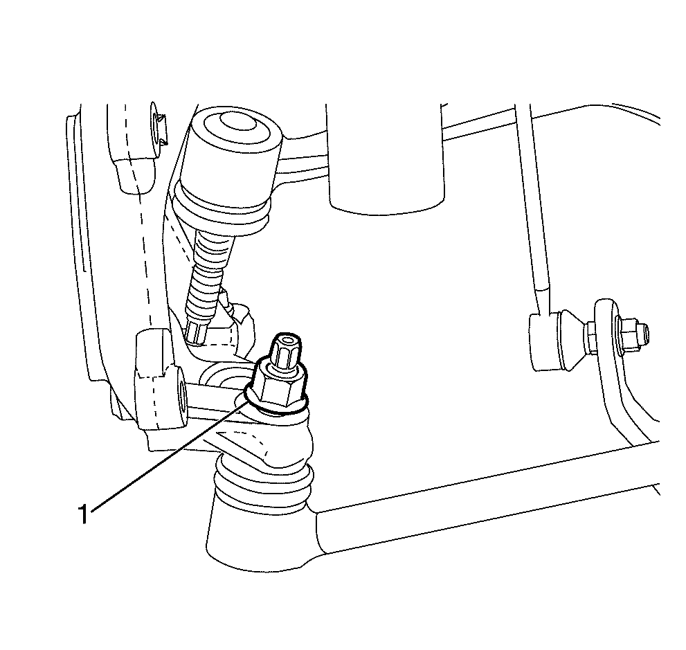
- Loosen the control arm to steering knuckle retaining nut (1) about two turns.
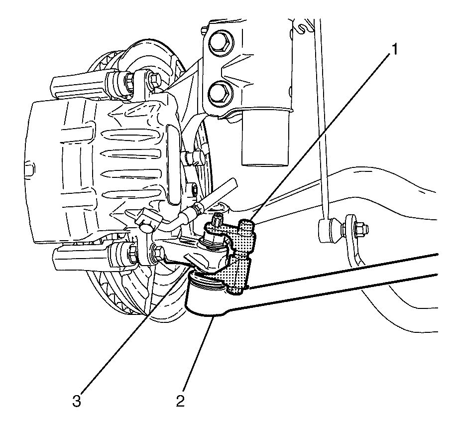
- Using J-42188-B (1) disconnect the control arm (2) from the steering knuckle (3).
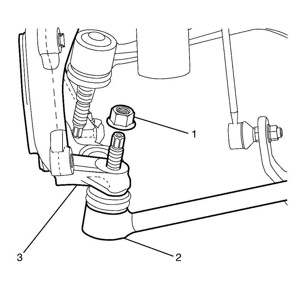
- Remove and discard the control arm to steering knuckle retaining nut (1).
- Separate the control arm (2) from the steering knuckle (3).
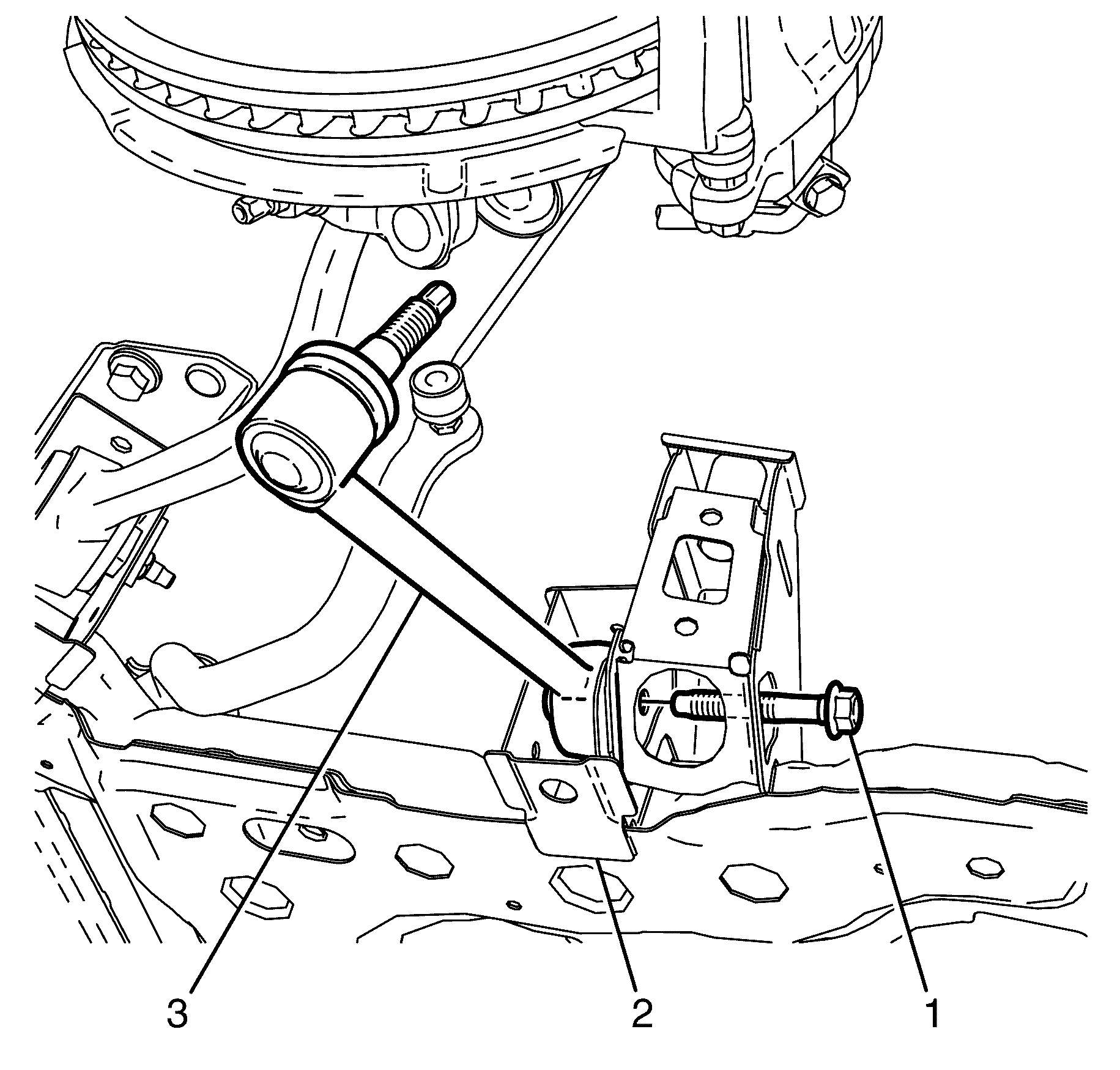
- Remove and discard the control arm to subframe retaining bolt (1).
- Remove the front control arm (3) from the subframe (2).
Warning: Refer to Safety Glasses Warning in the Preface section.
Danger: To avoid any vehicle damage, serious personal injury or death when major components are removed from the vehicle and the vehicle is supported by a hoist, support the vehicle with jack stands at the opposite end from which the components are being removed and strap the vehicle to the hoist.
Installation Procedure
- Install the front control arm (3) to the subframe (2).
- Install the NEW front control arm to subframe retaining bolt (1).
- Install the front control arm (1) to the steering knuckle (3).
- Install the NEW control arm to steering knuckle retaining nut (2).
- Install the front wheel. Refer to Tire and Wheel Removal and Installation.
- Lower the vehicle.
- Bounce the vehicle several times to settle the suspension.
- Check and adjust the wheel alignment. Refer to Wheel Alignment Measurement.
- Tighten the NEW control arm to subframe retaining bolt (1).

Note: The NEW front control arm to subframe retaining bolt (1) must not be fully tightened at this stage.
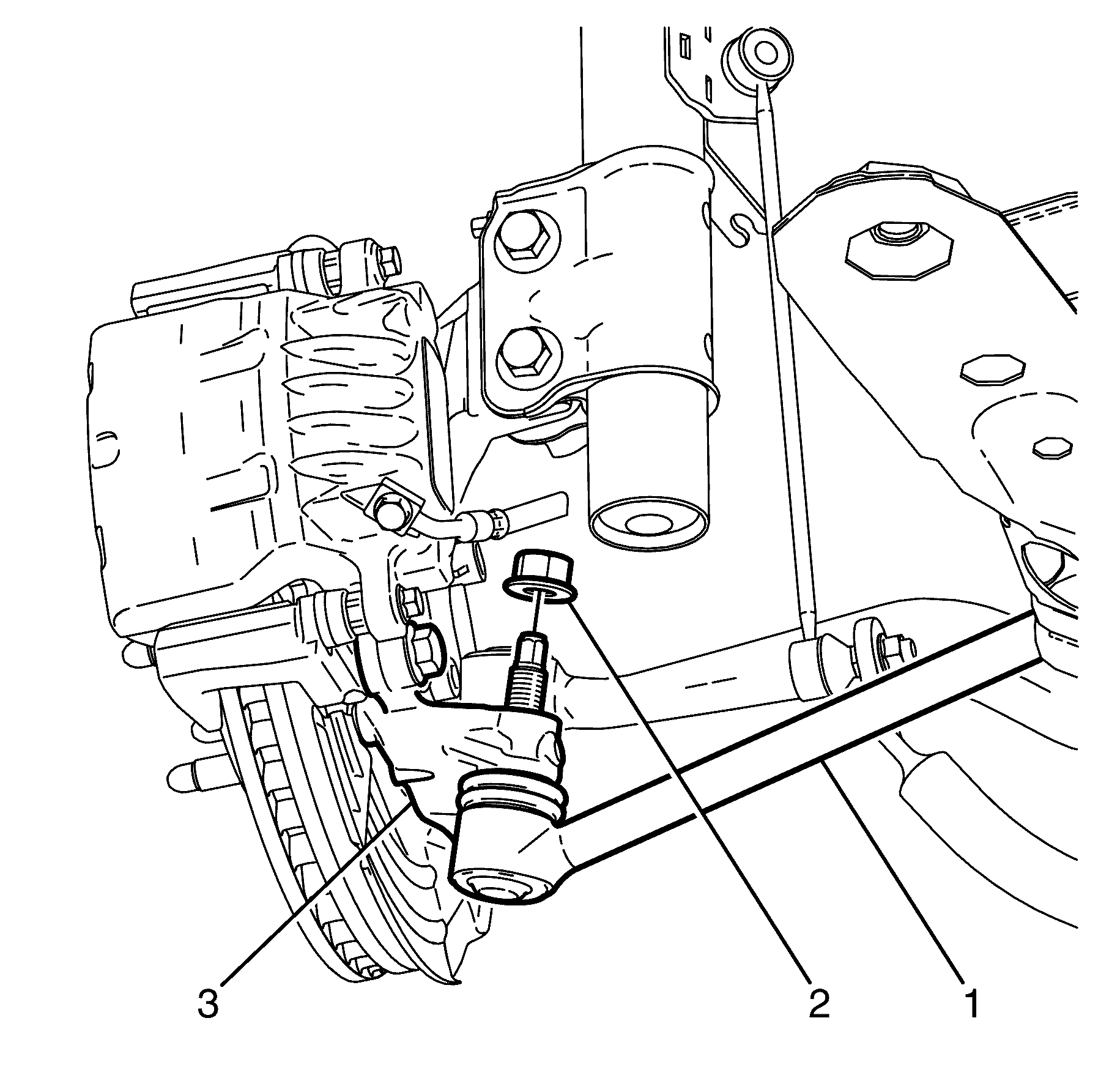
Caution: Refer to Fastener Caution in the Preface section.
Tighten
| • | First Pass: Tighten the nut to 40 N·m (30 lb ft) |
| • | Final Pass: Tighten the nut an additional 60 degrees using E7115 . |
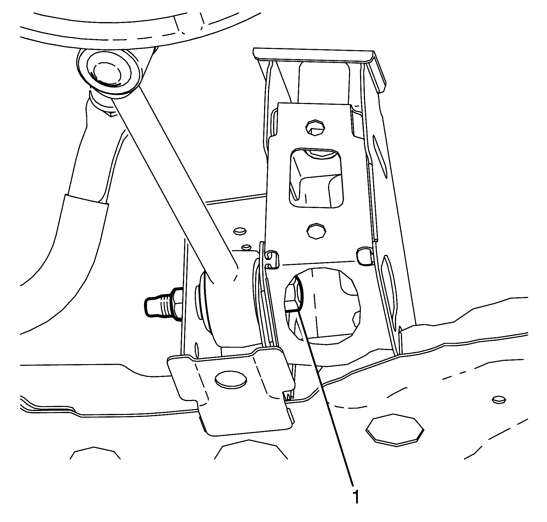
Tighten
| • | First Pass: Tighten the nut to 50 N·m (30 lb ft). |
| • | Final Pass: Tighten the nut an additional 120 degrees using E7115 |
