Servicing of the vehicle communication interface module (VCIM) will consist of either programming the VCIM via the OnStar® call centre or replacement of the VCIM.
Notice:
• Turn the ignition OFF when installing or removing the control module connectors and disconnecting or reconnecting the power to the control module (battery cable, powertrain control module (PCM)/engine control module (ECM)/transaxle control module
(TCM) pigtail, control module fuse, jumper cables, etc.) in order to prevent internal control module damage. • Control module damage may result when the metal case contacts battery voltage. DO NOT contact the control module metal case with battery voltage when servicing a control module, using battery booster cables, or when charging the vehicle battery. • In order to prevent any possible electrostatic discharge damage to the control module, do no touch the connector pins or the soldered components on the circuit board. • Remove any debris from around the control module connector surfaces before servicing the control module. Inspect the control module connector gaskets when diagnosing or replacing the control module. Ensure that the gaskets are installed correctly.
The gaskets prevent contaminant intrusion into the control module. • The replacement control module must be programmed.
Important: The VCIM once programmed, becomes permanently assigned to the vehicle identification number. A 10-digit station identification and an 11-digit electronic serial number, are used by the National Cellular Network carrier and OnStar® to identify the vehicle. Because these numbers are permanently assigned to the vehicle identification number, the VCIM must not be exchanged with that of another vehicle.
Removal Procedure
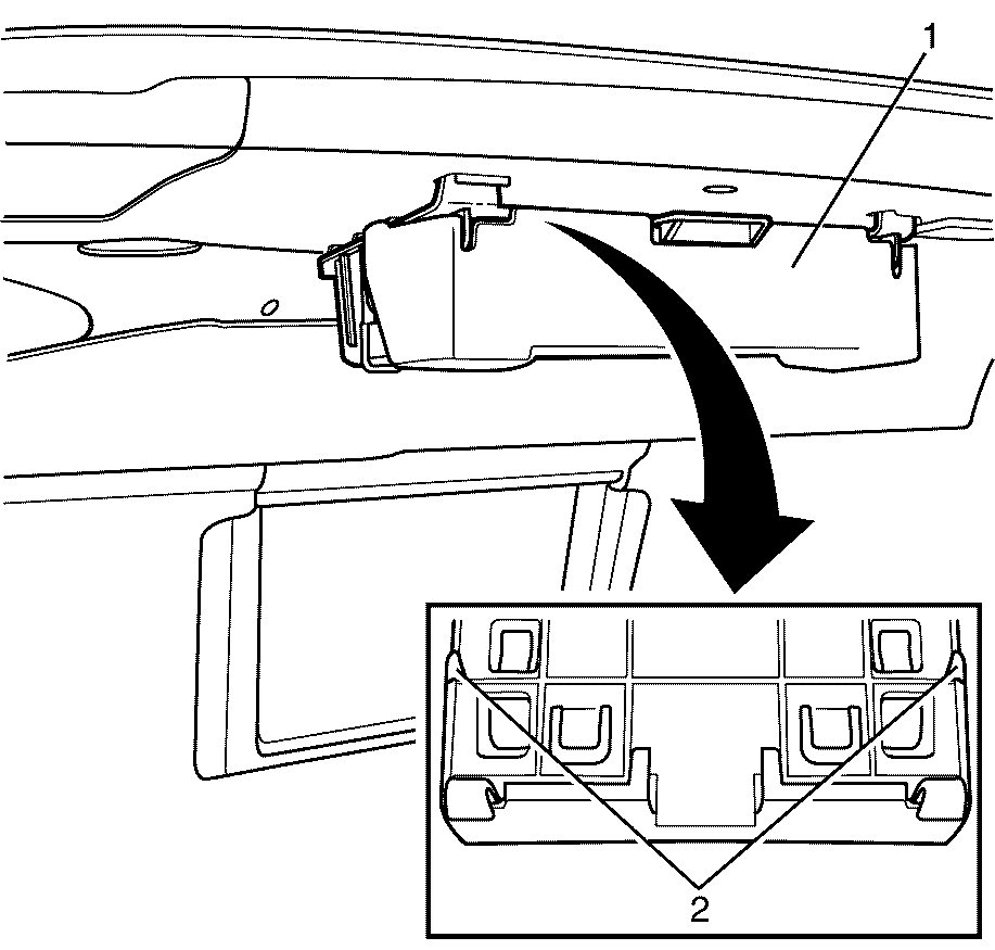
- Unclip the VCIM fascia cover (1) at the retaining clips (2) and remove the VCIM fascia cover (1) from the vehicle.
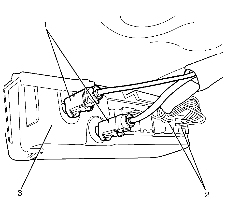
- Disconnect the antenna connectors (1) and the harness connectors (2) from the VCIM (3).
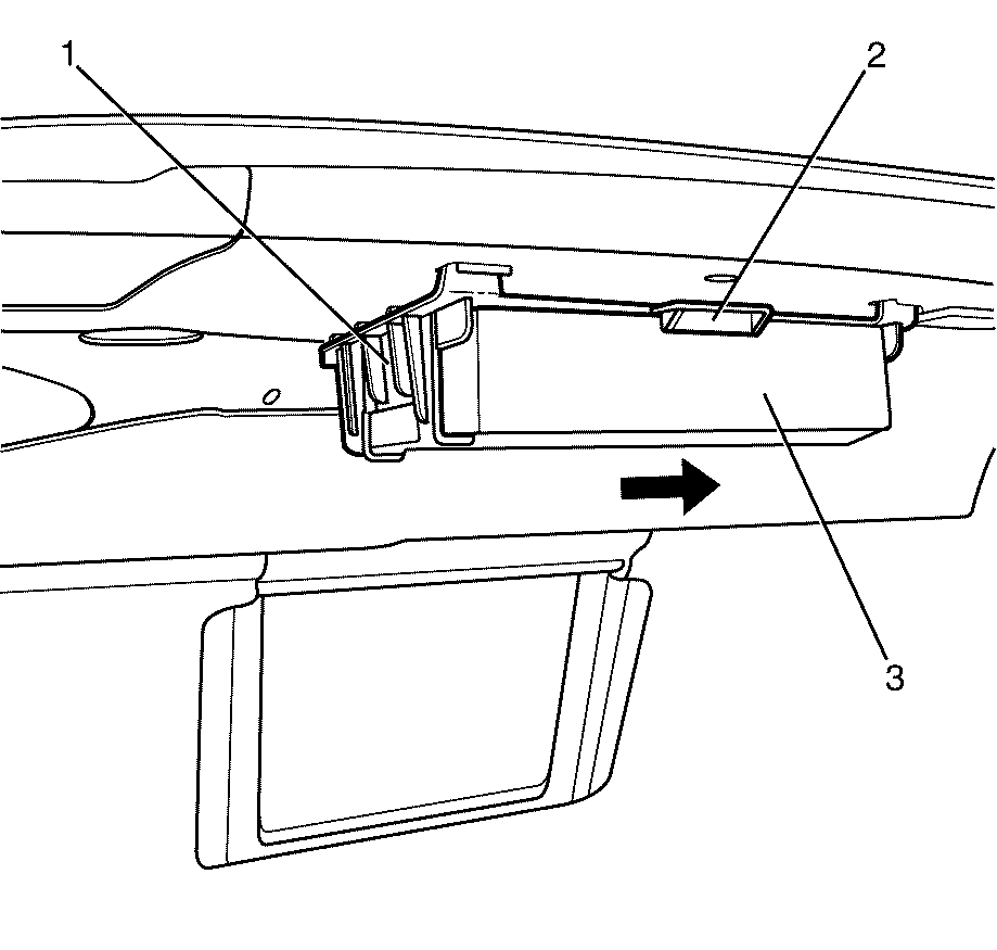
- Remove the VCIM (3) by pressing up on the retaining clip (2) and sliding the VCIM (3) out of the supporting bracket (1).


Installation Procedure
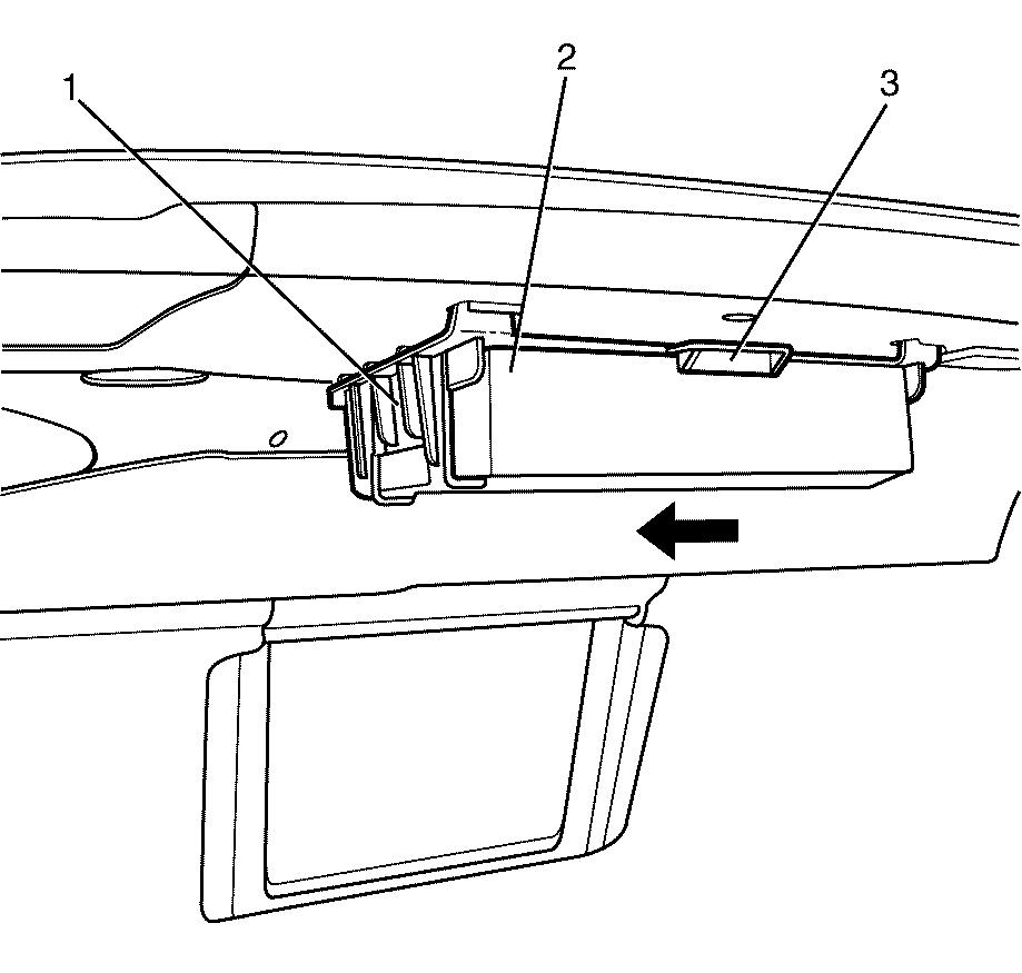
- Slide the VCIM (2) into the supporting bracket (1) and ensure that the retaining clip (3) locks the VCIM into place. Listen for an audible click to confirm correct fitting.
- Connect the antenna connectors (1) and the wiring harness connectors (2) to the VCIM (3).
- Install the cover (1) and make sure that the retaining clips (2) locks into place. Listen for an audible click to confirm fitting.
- Program the VCIM after replacement. Refer to Control Module References in Control Module References.


Important: After replacing the vehicle communication interface module, you must configure the OnStar® system.
