For 1990-2009 cars only
SMU - Revised Air Temperature Actuator Replacement and Mode Actuator Replacement Procedures

| Subject: | Revised Air Temperature Actuator Replacement and Mode Actuator Replacement Procedures |
| Models: | 2005 Pontiac G6 |
This bulletin is being issued to revise the Air Temperature Actuator Replacement procedure and the Mode Actuator Replacement procedure in the HVAC-Manual sub-section of the Service Manual. Please replace the current information in the Service Manual with the following information.
The following information has been updated within SI. If you are using a paper version of this Service Manual, please make a reference to this bulletin on the affected page.
Air Temperature Actuator Replacement
Removal Procedure
- Remove the fuse labeled HVAC CTRL (BATT).
- Completely open the instrument panel (I/P) compartment door by pressing both tabs that support the stop bumpers. Refer to Compartment Replacement - Instrument Panel (I/P).
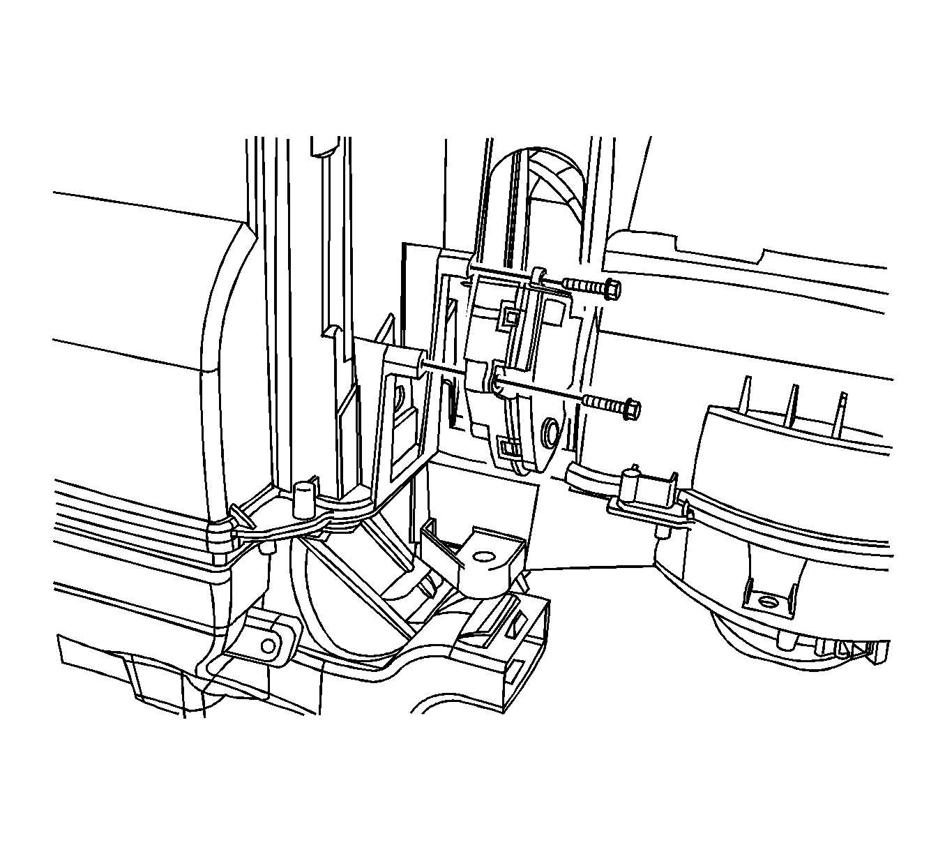
- Remove the air temperature actuator screws.
- Remove the air temperature actuator.
- Disconnect the air temperature actuator electrical connector.

Installation Procedure
- Connect the air temperature actuator electrical connector.
- Install the air temperature actuator.
- Install the air temperature actuator screws.
- Close the I/P compartment door. Refer to Compartment Replacement - Instrument Panel (I/P).
- Install the fuse labeled HVAC CTRL (BATT).

Notice: Refer to Fastener Notice in Cautions and Notices.
Tighten
Tighten the screws to 1.5 N·m (13 lb in).
Mode Actuator Replacement
Removal Procedure
- Remove the fuse labeled HVAC CTRL (BATT).
- Remove the left closeout panel. Refer to Closeout/Insulator Panel Replacement - Left.
- Remove the knee bolster. Refer to Knee Bolster Replacement.
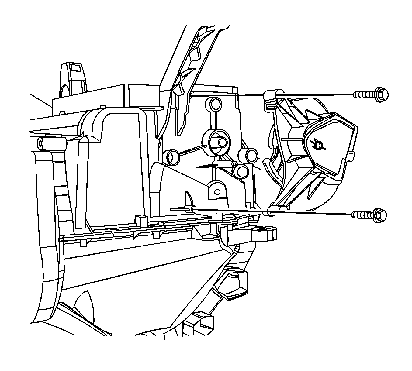
- Remove the mode actuator retaining screws.
- Remove the mode actuator.
- Disconnect the mode actuator electrical connector.

Installation Procedure
- Install the mode actuator.
- Install the mode actuator retaining screws.
- Connect the mode actuator electrical connector.
- Install the knee bolster. Refer to Knee Bolster Replacement.
- Install the left closeout panel. Refer to Closeout/Insulator Panel Replacement - Left.
- Install the fuse labeled HVAC CTRL (BATT).

Notice: Refer to Fastener Notice in Cautions and Notices.
Tighten
Tighten the screws to 1.5 N·m (13 lb in).
