| Table 1: | Backup Lamp Switch |
| Table 2: | Center High-Mounted Stop Lamp |
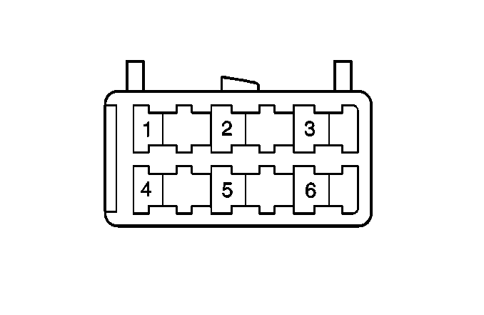
| Table 3: | Combination Lamp |
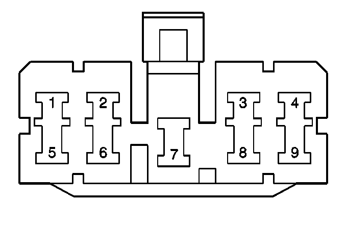
| Table 4: | Daytime Running Lamps (DRL) Control Module |
| Table 5: | Illumination Controller |
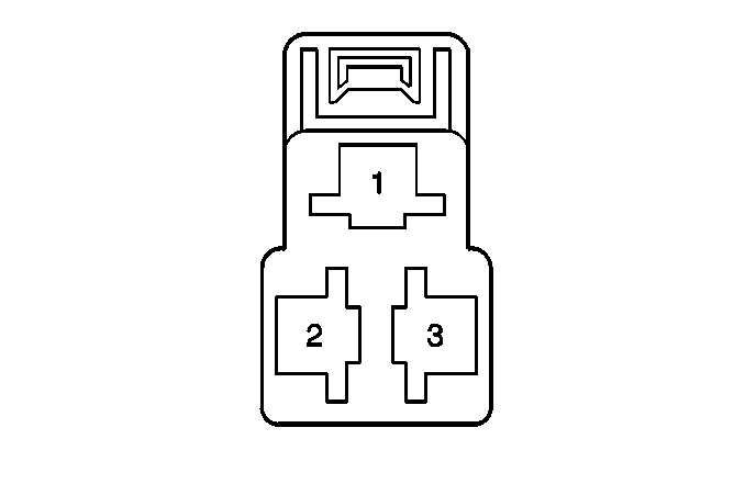
| Table 6: | Left Headlamp |
| Table 7: | LH Front Park/Turn Lamp |
| Table 8: | License Plate Lamp |
| Table 9: | Luggage Compartment Lamp |
| Table 10: | Park Lamp |
| Table 11: | Right Headlamp |
| Table 12: | RH Front Park/Turn Lamp |
| Table 13: | Stoplamp Switch (Automatic Transaxle) |
| Table 14: | Stoplamp Switch (manual transaxle) |
| Table 15: | Transaxle Range Switch |
| Table 16: | Turn Signal Combination Switch |

| ||||||
|---|---|---|---|---|---|---|
Connector Part Information |
| |||||
Pin | Wire Color | Function | ||||
1 | YEL | BACK Fuse | ||||
2 | RED | Ground | ||||
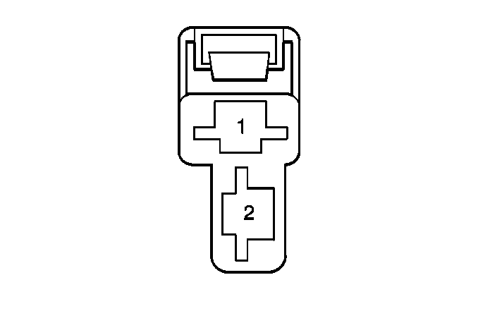
| ||||||
|---|---|---|---|---|---|---|
Connector Part Information |
| |||||
Pin | Wire Color | Function | ||||
1 | BLK | Stoplamp Switch | ||||
2 | GRN/WHT | Ground - G401 | ||||
| ||||||
|---|---|---|---|---|---|---|
Connector Part Information |
| |||||
Pin | Wire Color | Function | ||||
1 | BLK | Ground - G400 | ||||
2 | GRN/YEL | Turn | ||||
3 | RED/YEL | Tail Lamp/Side Marker | ||||
4 | RED | Backup Lamp | ||||
5 | GRN/WHT | Stoplamp Switch | ||||
6 | -- | Not Used | ||||
| ||||||
|---|---|---|---|---|---|---|
Connector Part Information |
| |||||
Pin | Wire Color | Function | ||||
1 | RED/ WHT | Low Beam | ||||
2 | ORN/ WHT | DRL Indicator Control | ||||
3 | PPL | Parking Brake Signal | ||||
4 | WHT/ RED | Charge Input Signal | ||||
5 | BLK/ WHT | Power Input | ||||
6 | -- | Not Used | ||||
7 | BLK | Ground - G201 | ||||
8 | RED/ BLK | BRAKE Indicator Control | ||||
9 | RED/ BLK | Headlamps On Signal | ||||
| ||||||
|---|---|---|---|---|---|---|
Connector Part Information |
| |||||
Pin | Wire Color | Function | ||||
1 | BLK | Ground | ||||
2 | RED/YEL | B+ | ||||
3 | RED/GRN | Instrument Panel Cluster Assy. Bulbs | ||||
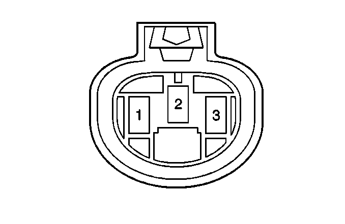
| ||||||
|---|---|---|---|---|---|---|
Connector Part Information |
| |||||
Pin | Wire Color | Function | ||||
1 | RED | High Beam | ||||
2 | WHT/BLU | H/L, L Fuse (DRL Diode) | ||||
3 | RED/WHT | Low Beam | ||||
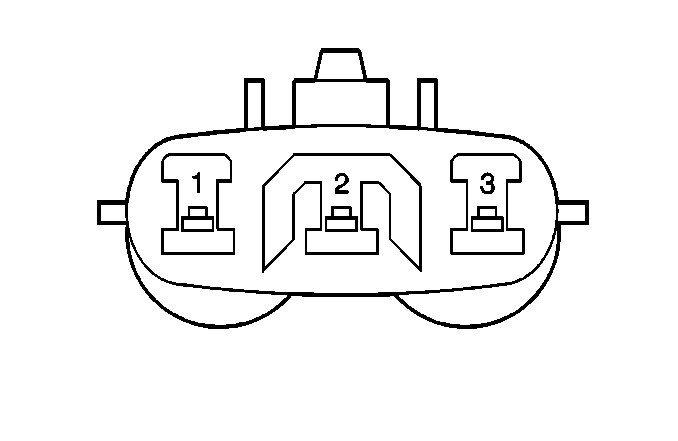
| ||||||
|---|---|---|---|---|---|---|
Connector Part Information |
| |||||
Pin | Wire Color | Function | ||||
1 | RED/YEL | Light 1 Relay | ||||
2 | BLK | Ground G103 | ||||
3 | GRN/RED | Turn Indicator | ||||
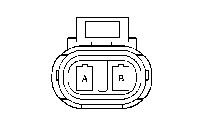
| ||||||
|---|---|---|---|---|---|---|
Connector Part Information |
| |||||
Pin | Wire Color | Function | ||||
A | RED/YEL | Interior Lights Dimming | ||||
B | BLK | Ground - G400 | ||||
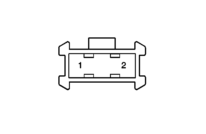
| ||||||
|---|---|---|---|---|---|---|
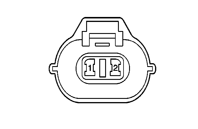
Connector Part Information |
| |||||
Pin | Wire Color | Function | ||||
1 | WHT | DOME Fuse | ||||
2 | BLK/YEL | Luggage Compartment Lamp Switch | ||||
| ||||||
|---|---|---|---|---|---|---|
Connector Part Information |
| |||||
Pin | Wire Color | Function | ||||
1 | RED/YEL | Light 1 Relay | ||||
2 | BLK | Ground G102 | ||||

| ||||||
|---|---|---|---|---|---|---|
Connector Part Information |
| |||||
Pin | Wire Color | Function | ||||
1 | RED | High Beam | ||||
2 | WHT/RED | H/L, L Fuse (DRL Diode) | ||||
3 | RED/WHT | Low Beam | ||||

| ||||||
|---|---|---|---|---|---|---|
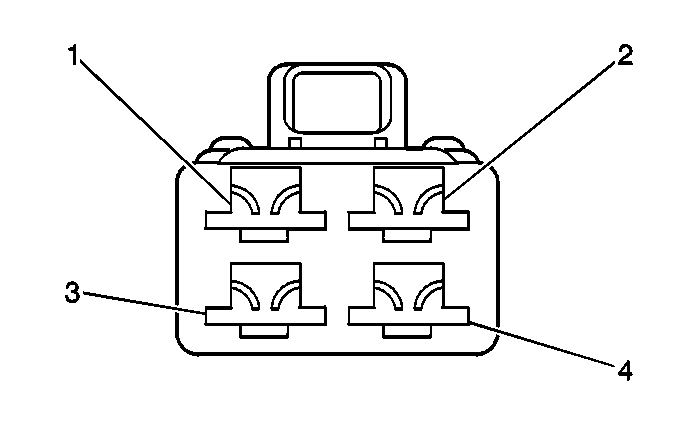
Connector Part Information |
| |||||
Pin | Wire Color | Function | ||||
1 | RED/YEL | Light 1 Relay | ||||
2 | BLK | Ground G103 | ||||
3 | GRN/YEL | Turn Indicator | ||||
| ||||||
|---|---|---|---|---|---|---|
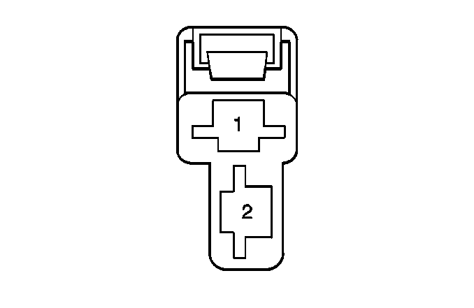
Connector Part Information |
| |||||
Pin | Wire Color | Function | ||||
1 | GRN/WHT | Electronic Brake Control Module (EBCM) | ||||
2 | -- | Not used | ||||
3 | WHT/YEL | Power | ||||
4 | -- | Not used | ||||
| ||||||
|---|---|---|---|---|---|---|
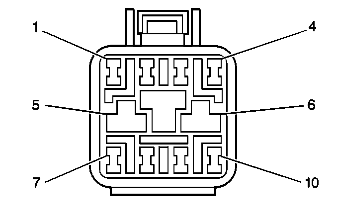
Connector Part Information |
| |||||
Pin | Wire Color | Function | ||||
1 | GRN/WHT | Brake Switch Input | ||||
2 | WHT/YEL | B+ | ||||
| ||||||
|---|---|---|---|---|---|---|
Connector Part Information |
| |||||
Pin | Wire Color | Function | ||||
1 | RED | R Position Signal | ||||
2 | GRN/RED | D Position Signal | ||||
3 | GRN | 2 Position Signal | ||||
4 | GRN/BLU | L Position Signal | ||||
5 | BLK/YEL | TR Switch Input/Starter Solenoid | ||||
6 | BLK/RED | Ign. Start | ||||
7 | -- | Not Used | ||||
8 | YEL | BACK Fuse | ||||
9 | ORN/BLK | P Position Signal | ||||
10 | ORN/YEL | N Position Signal | ||||
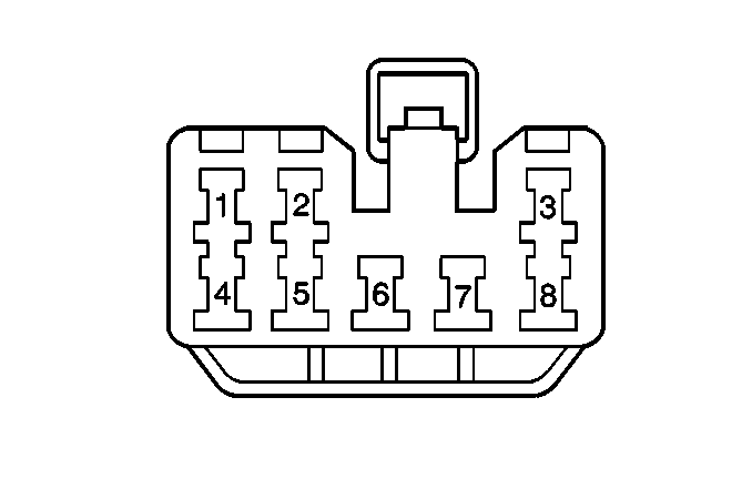
| ||||||
|---|---|---|---|---|---|---|
Connector Part Information |
| |||||
Pin | Wire Color | Function | ||||
1 | BLU/RED | Front Wiper Motor | ||||
2 | BLU/WHT | Wiper Park Signal | ||||
3 | RED/WHT | Low Beam | ||||
4 | BLU/BLK | Front Washer Pump | ||||
5 | BLU | Front Wiper Motor (Low) | ||||
6 | BRN/YEL | Light 2 Relay Switch | ||||
7 | RED/BLK | Light 2 Relay | ||||
8 | RED/GRN | Light 1 Relay | ||||
