- Use a socket and a hammer in order to install the new power steering pump shaft oil seal.
- Apply power steering fluid GM P/N 12346143 or equivalent to the pump shaft.
- Install the pump shaft pulley to the pump body.
- Apply power steering fluid GM P/N 12346143, or the equivalent, to the new O-rings.
- Install new O-rings to the pump body.
- Install the side plate to the pump body.
- Apply power steering fluid GM P/N 12346143, or the equivalent, to the sliding surface of the rotor.
- Install the rotor to the pump shaft.
- Install the snap ring (3) to the pump shaft groove.
- Apply power steering fluid GM P/N 12346143, or the equivalent, to the sliding surface of the cam ring.
- Install the cam ring (1) to the pump body.
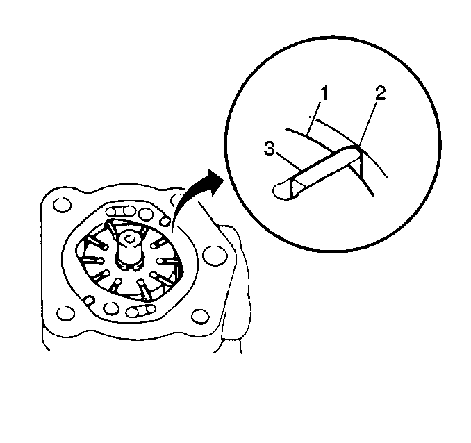
- Apply power steering fluid GM P/N 12346143, or the equivalent, to each vane plate.
- Install the vane plates (3) to the rotor with the R part of the vane (2) facing outward.
- Apply power steering fluid GM P/N 12346143, or the equivalent, to the O-ring at the pump body rear cover.
- Install the new O-ring to the rear of the pump body.
- Install the pump cover.
- Inspect the power steering pump shaft for smooth rotation and abnormal noise.
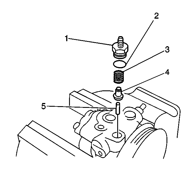
- Apply power steering fluid GM P/N 12346143, or the equivalent, to the relief valve.
- Install the relief valve spring and the relief valve to the pump body.
- Verify that the relief valve slides smoothly.
- Apply power steering fluid GM P/N 12346143, or the equivalent, to the O-rings at the high pressure line connector.
- Install the new O-rings to the high pressure line connector.
- Install the pressure line connector to the pump body.
- Apply power steering fluid GM P/N 12346143, or the equivalent, to the O-rings at the pressure sensor.
- Install the new O-ring (2) to the pressure sensor (1).
- Install the pressure sensor to the pump body.
- Apply power steering fluid GM P/N 12346143, or the equivalent, to the O-rings at the inlet pipe.
- Install the new O-ring to the inlet pipe.
- Install the inlet pipe to the pump. Secure the pipe with the 2 bolts.
- Remove the power steering gear pump from the soft jaw vise.
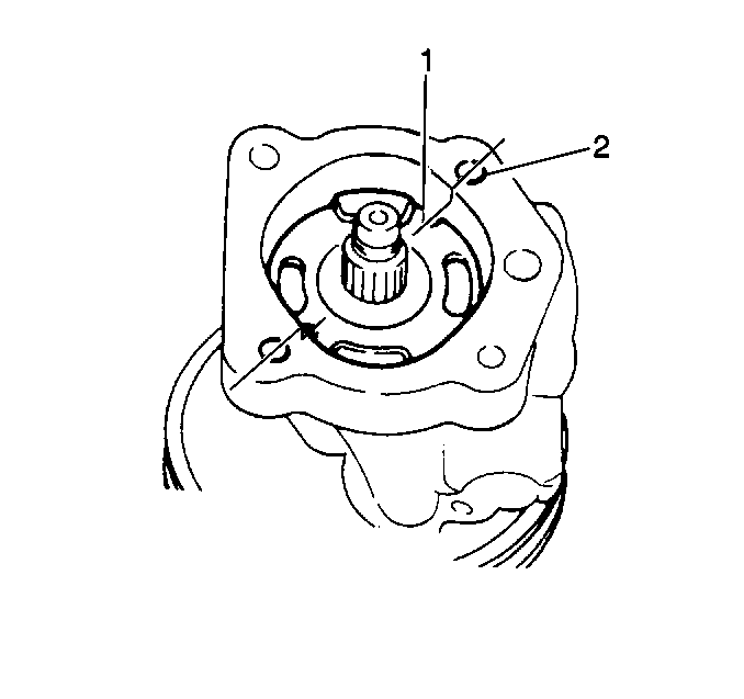
Align the pin grooves (1) of the side plate with the cover bolt holes (2).
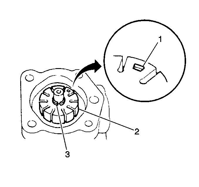
Direct the dent marked side of the rotor (1) toward the pump cover.
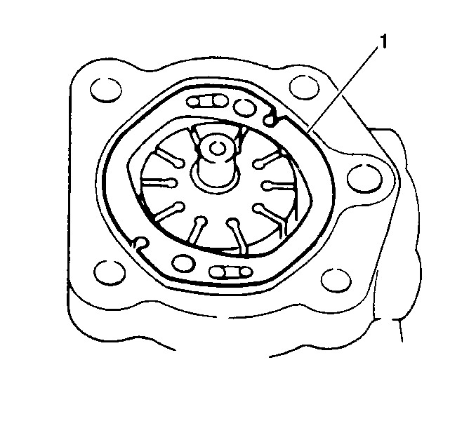
Direct the 5 marked side of the cam ring towards the side plate.
Notice: Use the correct fastener in the correct location. Replacement fasteners must be the correct part number for that application. Fasteners requiring replacement or fasteners requiring the use of thread locking compound or sealant are identified in the service procedure. Do not use paints, lubricants, or corrosion inhibitors on fasteners or fastener joint surfaces unless specified. These coatings affect fastener torque and joint clamping force and may damage the fastener. Use the correct tightening sequence and specifications when installing fasteners in order to avoid damage to parts and systems.
Secure the pump cover with the 4 bolts.
Tighten
Tighten the pump cover bolts to 24 N·m (17.5 lb ft).
If the power steering pump does not rotate smoothly or if you hear abnormal noise, disassemble and inspect the power steering pump shaft. Refer to Power Steering Pump Disassemble .
Tighten
Tighten the high pressure line connector to 60 N·m (44 lb ft).
Tighten
Tighten the pressure sensor to 18 N·m (13 lb ft).
Tighten
Tighten the inlet pipe bolts to 8 N·m (71 lb in).
