Removal Procedure
Tools Required
| • | J 28467-A Universal Support Fixture |
| • | J 28467-89 Universal Support Fixture Adapters |
| • | J 28712 Drive Axle Boot Protectors |
- Disconnect the negative battery cable (3).
- Remove the hood bolts and the hood with assistants.
- Remove the battery hold-down bolt and the hold-down bracket.
- Remove the battery.
- Disconnect the transaxle electrical connectors.
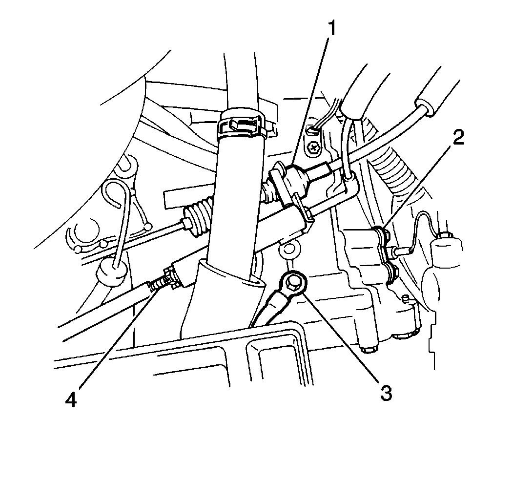
- Disconnect the speedometer cable.
- Remove the TV cable adjustment cover and the TV cable (4) from the accelerator cable.
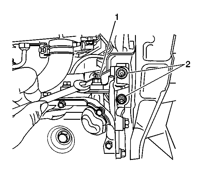
- Remove the adjustment nut (1) from the end of the shift select cable.
- Remove the shift select cable from the manual select cable joint.
- Remove the 1 retaining clip and the shift select cable from the bracket.
- Loosen the accelerator cable adjustment nuts.
- Disconnect the accelerator cable from the bracket.
- Remove the harness from the bracket (2) from the rear of the transaxle case.
- Disconnect the electrical connectors from the following:
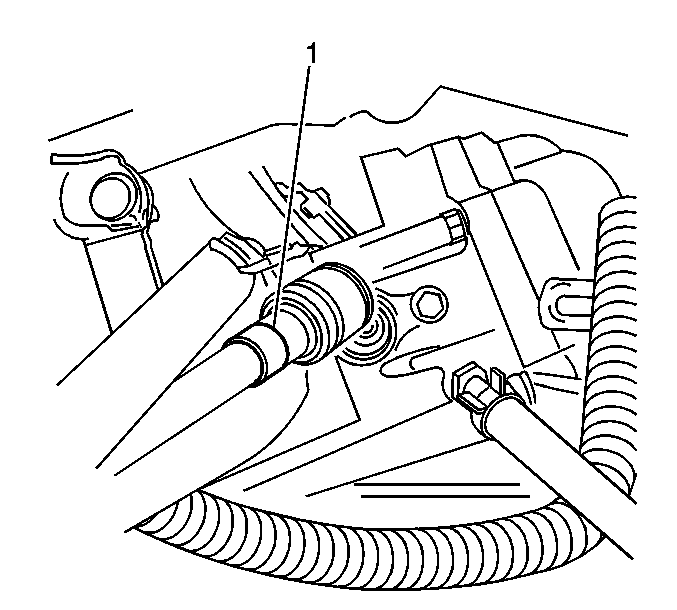
- Remove the 1 retaining clip and the speedometer cable (1) from the speedometer driven gear case.
- Disconnect the starter electrical connections.
- Remove the starter bolts.
- Remove the starter and the spacer plate.
- Remove the following components from the cooler pipes:
- Remove the upper rear bolt that mounts the transaxle to the bulkhead.
- Remove the 2 upper transaxle-to-engine retaining bolts from the transaxle.
- Remove the bolt and the negative battery cable (3) from the transaxle case.
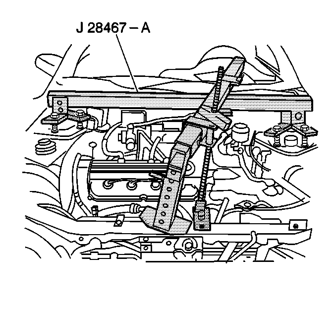
- Install and support the engine with theJ 28467-A and with the J 28467-89 .
- Raise and suitably support the vehicle. Refer to Lifting and Jacking the Vehicle in General Information.
- Remove the front wheel assemblies. Refer to Tire and Wheel Removal and Installation in Tires and Wheels.
- Place a drain pan or a suitable container under the transaxle fluid pan.
- Remove the transaxle drain plug in order to drain the transaxle fluid.
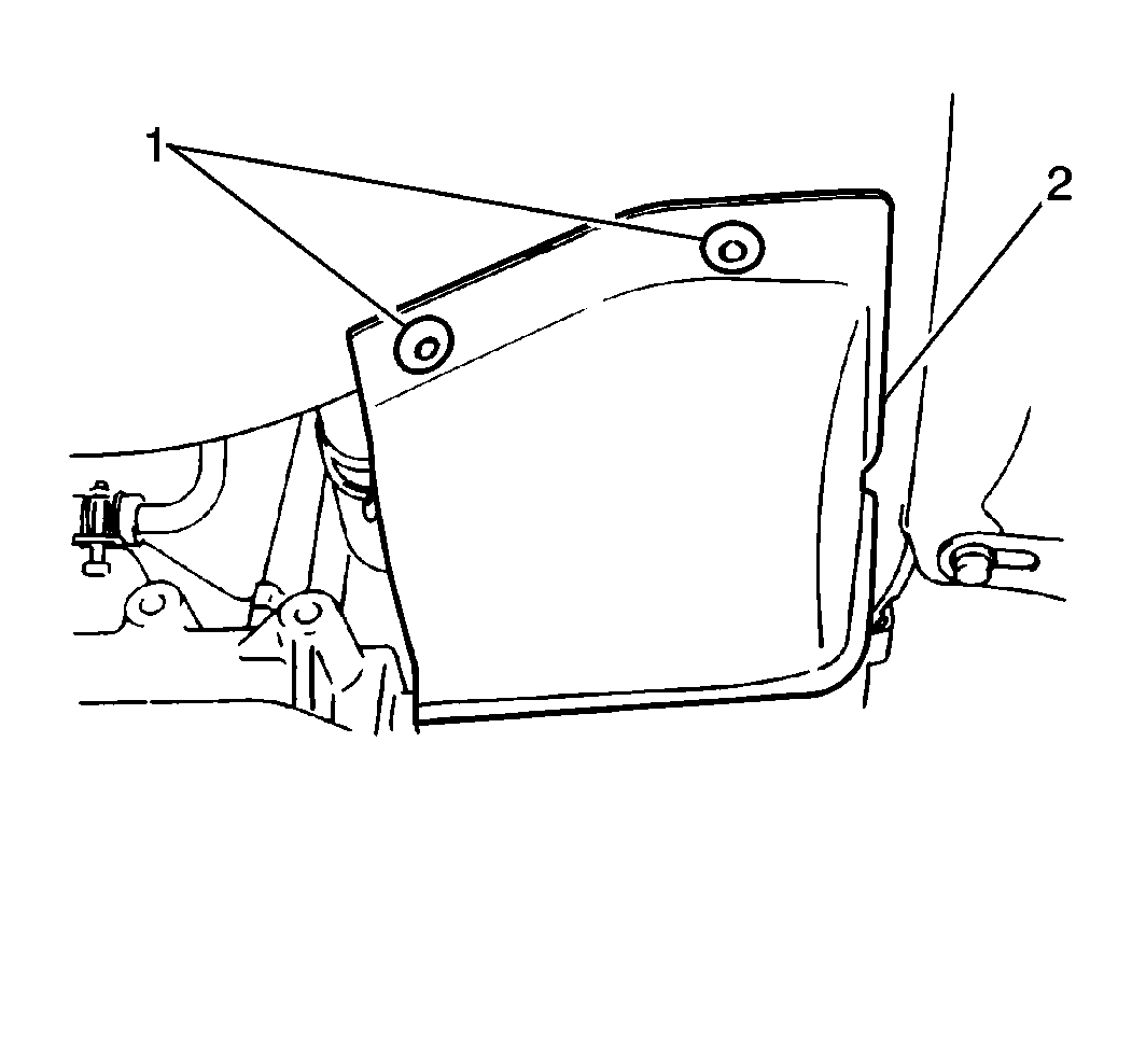
- Remove the 12 retaining clips (1) and the splash shields (2) from the vehicle.
- Remove the right and the left ball stud bolts.
- Separate the control arms from the steering knuckles.
- Install J 28712 the on the differential-side joints and on the wheel-side joints of both drive axles.
- Remove the right and the left drive axle assemblies from the vehicle. Refer to Wheel Drive Shaft Replacement in Wheel Drive Shafts.
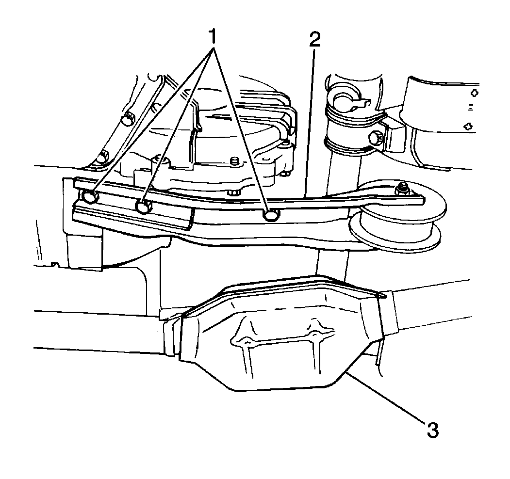
- Remove the 3 bolts (1) and the rear engine torque rod (2) from the transaxle case.
- Remove the 2 bolts and the flywheel cover from the transaxle case housing (3).
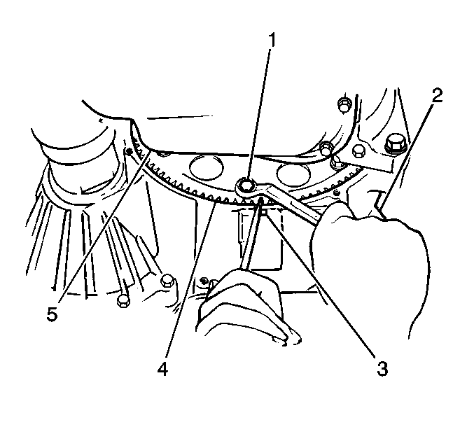
- Remove the 6 flywheel-to-torque converter bolts (1) from the flywheel (5).Lock the flywheel using a standard flat-bladed tool through the slot at the underside of the transaxle case housing.
- Remove the muffler mounting bracket from the exhaust hanger at the rear of the engine.
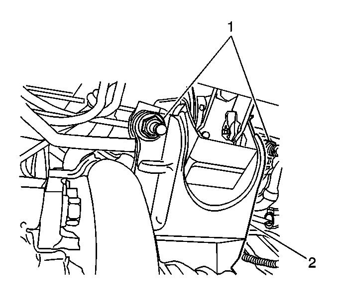
- Remove the 2 nuts (1) and the 2 bolts, and the rear engine mount bracket (2) from the transaxle.
- Lower the vehicle.
- Lower the engine slightly with the .
- Raise the J 28467-A vehicle.
- Support the transaxle with a suitable hydraulic jack.
- Remove the 2 retaining nuts (1) from the left transaxle mount (2).
- Remove the 2 bolts, the left transaxle mount, and the bracket from the transaxle.
- Remove the lower engine-to-transaxle bolt and the nut.
- Remove the 1 transaxle stud from the transaxle.
- Remove the transaxle from the engine.
Caution: Unless directed otherwise, the ignition and start switch must be in the OFF or LOCK position, and all electrical loads must be OFF before servicing any electrical component. Disconnect the negative battery cable to prevent an electrical spark should a tool or equipment come in contact with an exposed electrical terminal. Failure to follow these precautions may result in personal injury and/or damage to the vehicle or its components.
| • | The Vehicle Speed Sensor (VSS). |
| • | The Shift Solenoid. |
| • | The PNP Switch. |
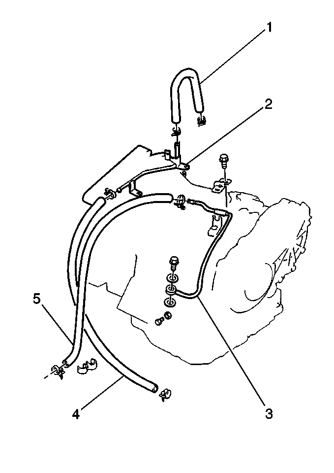
Important: Plug the fluid cooler hoses in order to prevent transaxle cooler leakage.
| • | The 2 hose clamps |
| • | The inlet fluid cooler hose (1,4) |
| • | The outlet fluid cooler hose (5) |

Notice: J 28712 should be installed on any drive axle prior to service procedures on or near the drive axle. Failure to observe this can result in boot damage and possible joint failure. Refer to Drive Axle for information on the J 28712 and for proper drive axle removal and handling procedures.
Installation Procedure
Tools Required
| • | J 28467-A Universal Support Fixture |
| • | J 28467-89 Universal Support Fixture Adapters |
| • | J 28712 Drive Axle Boot Protectors |
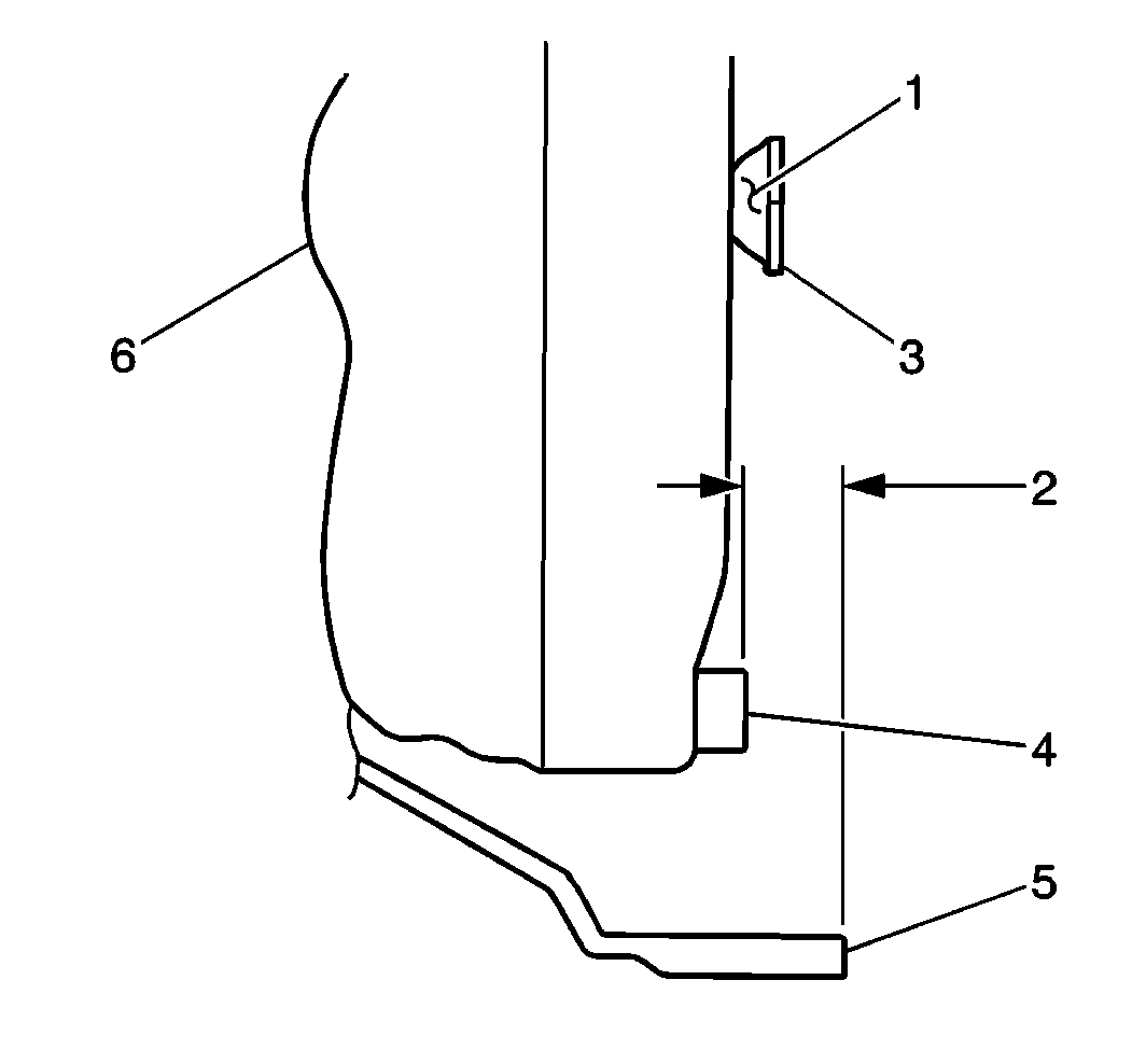
- Measure the distance (2). The distance should be more than 21.4 mm (0.85 in). If the distance is less than 21.4 mm (0.85 in), the torque converter is incorrectly installed. Reseat correctly the torque converter onto the input shaft.
- Use the following steps in order to install the transaxle to the engine block:
- Install the transaxle stud to the transaxle.
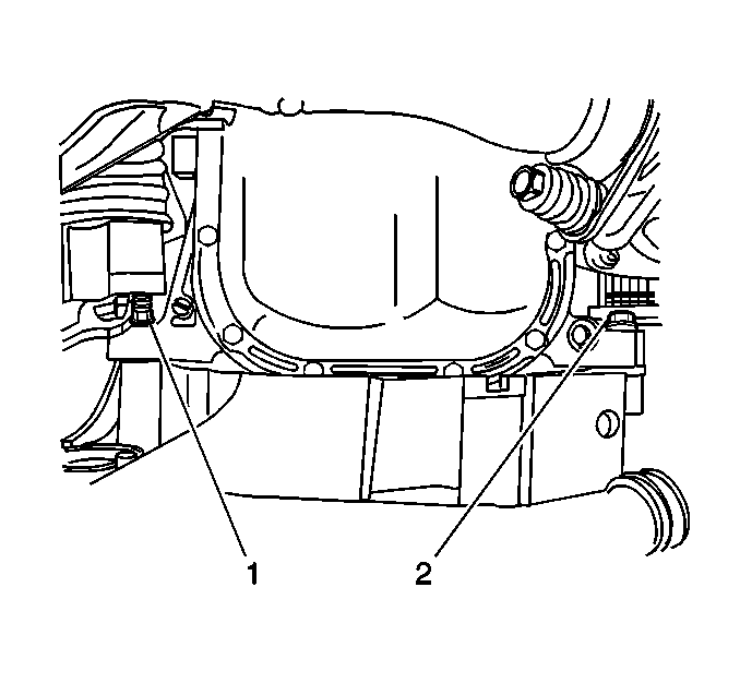
- Install the lower engine-to-transaxle bolt (2) and the nut (1).
- Install the left transaxle mount and the bracket to the transaxle. Secure the transaxle mount and the bracket with the 2 bolts (1).
- Install the 2 nuts (2) to the left transaxle mount.
- Remove the hydraulic jack from under the transaxle.
- Lower the vehicle.
- Raise the engine with the J 28467-A .
- Raise the vehicle.
- Install the rear engine mount bracket (2) to the transaxle. Secure the bracket with the 2 bolt and with the 2 nuts.
- Install the rear engine mount to the bulkhead. Secure the rear engine mount to the bulkhead with the lower bolt.
- Install the 6 flywheel-to-torque converter bolts. In order to lock the flywheel (4), engage a standard flat-bladed tool with the flywheel ring gear through the slot (3) at the underside of the transaxle case housing.
- Install the flywheel cover to the transaxle case housing. Secure the cover with 2 bolts.
- Install the drive axle assemblies into the vehicle. Refer to Wheel Drive Shaft Replacement in Wheel Drive Shafts.
- Install the torque rod (2) to the transaxle case. Secure the torque rod with the 3 bolts (1) .
- Install the control arms to the steering knuckles. Secure the control arms with the ball stud bolts. Refer to Lower Control Arm Replacement .
- Install the splash shields (2) to the vehicle. Secure the splash shields with the 12 retaining clips (1).
- Install the transaxle drain plug into the transaxle fluid pan.
- Install both front wheels. Refer to Tire and Wheel Removal and Installation in Tires and Wheels.
- Lower the vehicle.
- Remove the J 28467-89 and the J 28467-A .
- Connect the negative battery cable to the transaxle case. Secure the negative battery cable with the bolt.
- Install the 2 upper transaxle-to-engine bolts.
- Install the bolt to the upper rear transaxle mount and to the bulkhead.
- Raise the vehicle.
- Install the starter motor to the transaxle. Secure the motor with the 2 bolts.
- Connect the electrical connectors to the starter motor.
- Lower the vehicle.
- Connect the inlet and the outlet fluid cooler hoses (1,5) to the fluid cooler pipes (3) . Secure the hoses with the 2 clamps.
- Install the speedometer cable (1) into the speedometer driven gear case. Secure the speedometer cable with the clip.
- Connect the connectors to the VSS, to the shift solenoid wiring harness, and to the PNP switch.
- Install the engine wiring harness bracket (2) to the rear of the transaxle case. Secure the bracket with 2 bolts.
- Install the accelerator cable into the bracket.
- Install the accelerator cable adjustment nuts.
- Install the shift select cable (1) into the bracket. Secure the bracket with 1 retaining clip.
- Install the shift select cable end into the manual select cable joint.
- Adjust the shift select cable. Refer to Range Selector Lever Cable Replacement .
- Install the TV cable (4) to the accelerator cable. Refer to Automatic Transmission Throttle Valve Cable Replacement .
- Adjust the TV cable. Refer to Automatic Transmission Throttle Valve Cable Adjustment ,
- Install the TV cable adjustment cover.
- Install the negative battery cable (3).
- Refill the transaxle, as necessary. Refer to Transmission Fluid Check .
Notice: Automatic transmission oil cooler flushing must be performed when an automatic transmission is removed for service. The flushing procedure should be performed after the installation of the overhauled or replacement transmission. Failure to flush the system may cause damage to the system and its components.
Important: Before installing the transaxle assembly, apply some lubricant around the cup at the center of the torque converter (1). This will ensure ease of assembly. Use the following steps in order to install the transaxle to the engine block:
| 2.1. | Use a suitable hydraulic jack in order to carefully raise the transaxle. |
| 2.2. | Clear any obstructions. |
Install the transaxle to the engine block.
Notice: Use the correct fastener in the correct location. Replacement fasteners must be the correct part number for that application. Fasteners requiring replacement or fasteners requiring the use of thread locking compound or sealant are identified in the service procedure. Do not use paints, lubricants, or corrosion inhibitors on fasteners or fastener joint surfaces unless specified. These coatings affect fastener torque and joint clamping force and may damage the fastener. Use the correct tightening sequence and specifications when installing fasteners in order to avoid damage to parts and systems.
Tighten
Tighten the lower engine-to-transaxle bolt and the nut to 55 N·m (40
lb ft).

Tighten
Tighten the bolts to 55 N·m (40 lb ft).
Tighten
Tighten the nuts to 55 N·m (40 lb ft).

Tighten
Tighten the bolts and the nuts (1) to 55 N·m (40 lb ft).
Tighten
Tighten the bolt to 55 N·m (40 lb in).

Tighten
Tighten the flywheel-to-torque converter bolts to 19 N·m (14 lb ft).
Tighten
Tighten the flywheel cover bolts to 10 N·m (89 lb in).
Remove the J 28712 from the differential-side joints and from the wheel-side joints of both drive axles.

Tighten
Tighten the bolts of the rear engine torque rod to 55 N·m (40 lb ft).
Tighten
Tighten the ball bolts to 60 N·m (44 lb ft).

Tighten
Tighten the transaxle drain plug to 23 N·m (17 lb ft).

Tighten
Tighten the bolt to 15 N·m (11 lb ft).
Tighten
Tighten the bolts to 55 N·m (40 lb ft).
Tighten
Tighten the bolt to 55 N·m (40 lb ft).
Tighten
Tighten the starter motor retaining bolts to 23 N·m (17 lb ft).


Tighten
Tighten the bolts to 16 N·m (12 lb ft).
Secure the shift select cable end with the adjustment nut.
