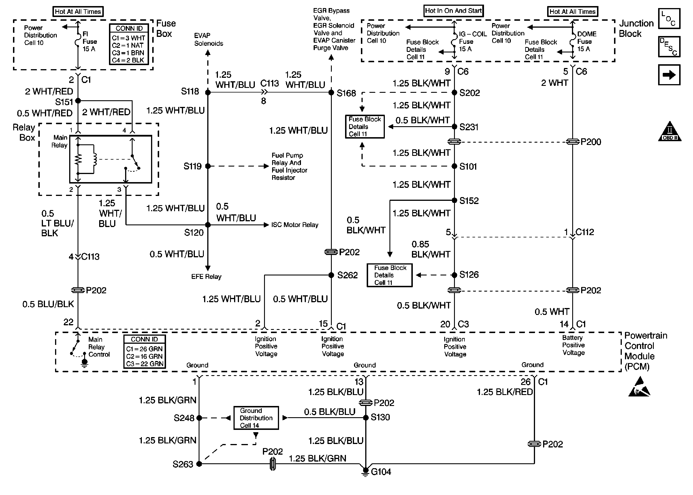
Refer to
Cell 20: Power and Ground

.
Circuit Description
The main relay is controlled by the powertrain control module (PCM). The PCM provides a ground for the relay's coil anytime the ignition switch is ON. The main relay supplies ignition positive voltage to many engine control systems and components. The following components receive power from the main relay:
| • | The fuel pump relay |
| • | The EFE relay |
| • | The fuel injector |
| • | The EVAP control system solenoids |
| • | The EGR system solenoids |
| • | The idle speed control (ISC) motor |
| • | The powertrain control module (PCM) |
Diagnostic Aids
Check for any of the following conditions:
| • | Check the resistance of the main relay. The resistance across terminal 1 and terminal 2 is 79-95 ohms at 20°C (68°F). The resistance across terminal 3 and terminal 4 is infinite. |
| • | The main relay's electrical contacts may be pitted or sticking. Replace the main relay if tapping gently on the relay or wiggling the relay causes a change in the relay's operation. |
| • | The performance of the main relay may be affected by temperature. Check the main relay after sitting outside overnight and after running the engine 30 minutes. |
| • | Check for a faulty electrical connection to the PCM. |
An intermittent malfunction may be caused by a fault in the main relay electrical circuit. Inspect the wiring harness and components for any of the following conditions:
| • | Backed out terminals |
| • | Improper mating of terminals |
| • | Broken electrical connector locks |
| • | Improperly formed or damaged terminals |
| • | Faulty terminal to wire connections |
| • | Physical damage to the wiring harness |
| • | A broken wire inside the insulation |
| • | Corrosion of electrical connections, splices, or terminals |
Use the following relay cavity table in order to locate the correct cavities to probe during diagnosis. The table layout corresponds to the cavity layout of the relay block.
Relay Cavity Identification | |
|---|---|
Switch Power | |
Switch Load | |
Coil Power | Coil Ground |
Test Description
The numbers below refer to the step numbers in the diagnostic table.
-
The Powertrain OBD System Check requires the technician to complete some basic checks and to store the freeze frame data on the scan tool. This creates an electronic copy of the data when the fault occurred. The information is stored in the scan tool for later reference.
-
This step will verify if the PCM is not providing a ground path for the main relay circuit. If terminal 2 of the main relay is grounded, the main relay turns ON.
-
This step checks for an ignition positive voltage at the PCM. The PCM will not operate the main relay if terminal C3-C20 does not have power.
-
This step checks for an open in the PCM electrical grounds. The PCM will not operate the main relay if there are not electrical grounds.
Step | Action | Value(s) | Yes | No | ||||
|---|---|---|---|---|---|---|---|---|
Did you perform the Powertrain On-Board Diagnostic (OBD) System Check? | -- | |||||||
2 | Check for an open in the following fuses:
Was an open fuse found? | -- | ||||||
3 |
Was the relay clicking? | -- | Go to Diagnostic Aids | |||||
4 |
Does the test lamp illuminate? | -- | ||||||
5 | Connect a test lamp to ground. Probe terminal 1 of the main relay on the relay box side. Does the test lamp illuminate? | -- | ||||||
Does the test lamp illuminate? | -- | |||||||
7 | Repair the open in the ignition positive voltage circuit between the FI fuse and the main relay. Refer to Wiring Repairs in Wiring Systems. Is the action complete? | -- | -- | |||||
8 |
Was a repair necessary? | -- | ||||||
Does the test lamp illuminate? | -- | |||||||
10 | Repair the open in the ignition positive voltage circuit between the IG-COIL fuse and the PCM. Refer to Wiring Repairs in Wiring Systems. Is the action complete? | -- | -- | |||||
Does the test lamp illuminate at each ground terminal? | -- | |||||||
12 |
Is the action complete? | -- | -- | |||||
13 | Repair the short to ground in the IG-COIL fuse circuit or in the FI fuse circuit. Refer to Wiring Repairs in Wiring Systems. Is the action complete? | -- | -- | |||||
14 | Replace the main relay. Refer to Main Relay Replacement . Is the action complete? | -- | -- | |||||
15 | Replace the PCM. Refer to Powertrain Control Module Replacement . Is the action complete? | -- | -- | |||||
16 | Operate the vehicle within the conditions under which the original concern was noted. Does the system operate correctly? | -- | System OK | Go to the applicable DTC table |
