Power Folding Top Bow Replacement Folding Top Number 1 Bow
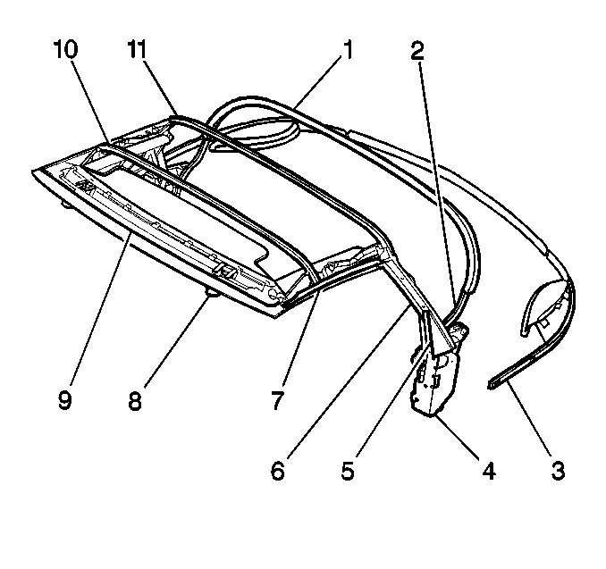
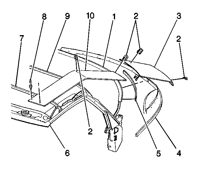
The five bow (3) run from one outboard side of the vehicle to the other. The bow support the folding top and maintain the shape of the folding top. The bow are numbered from front to rear. The number 1 bow is attached to the windshield header (9). The fixed-position number 5 bow serves as the rear tack strip (3).
Removal Procedure
- Remove the lower folding top to a suitable working position.
- Turn the pump bypass valve fully clockwise to the open position.
- Remove the side rail garnish molding. Refer to Folding Top Side Front Weatherstrip Replacement .
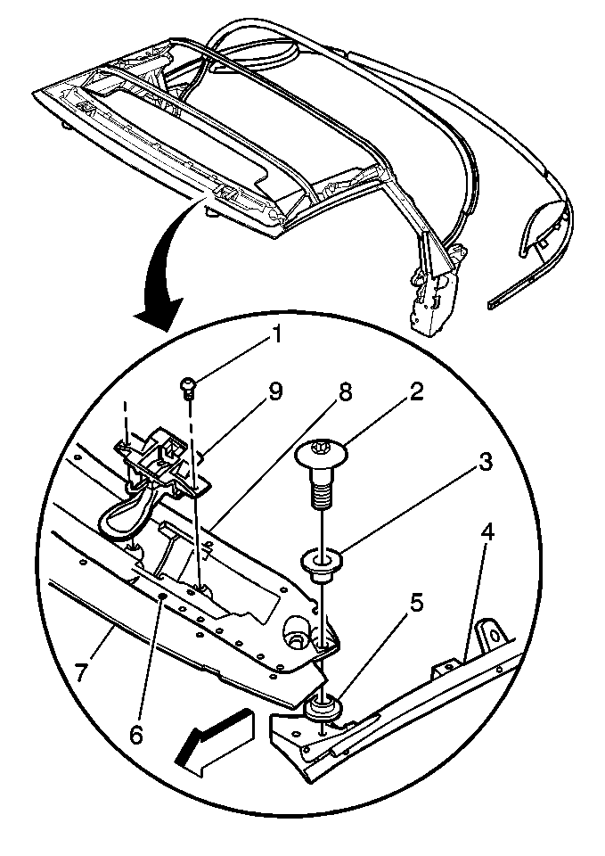
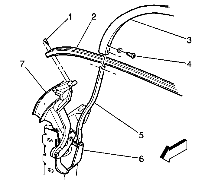
- Remove the number 1 bow garnish molding bolt (3).
- Remove the number 1 garnish molding (2).
- Remove the rivets at each corner of the headlining trim finish panel (3).
- Peel the headlining trim finish panel away from the adhesion in order to remove the headlining trim finish panel (3) from the number 1 bow (4).
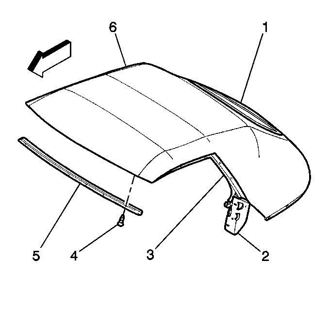
- Mark the top cover in order to show the leading edge of the number 1 bow (4).
- Remove the front cover number 1 bow retainer bolt (4).
- Remove the front cover number 1 bow retainer (5).
- Peel the cover away from the adhesive in order to remove the cover from the number 1 bow (6).
- Remove the black tape covering the side front stay rivets (8).
- Remove the side front stay rivets (8).
- Remove the number 1, 2, 3, and 4 bow position pad (10).
- Remove the number 1 bow links (8) from the number 1 bow (9) by punching out the pins.
- Remove the number 1 bow bolts (2) and bushings (3).
- Remove the number 1 bow (8).
- Remove the old adhesive from the side rail weatherstrip and the number 1 bow (8).
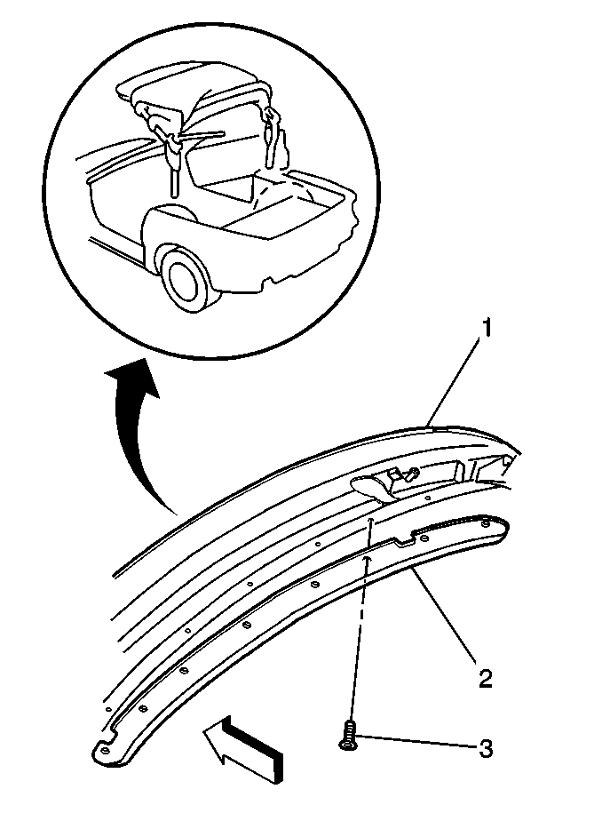
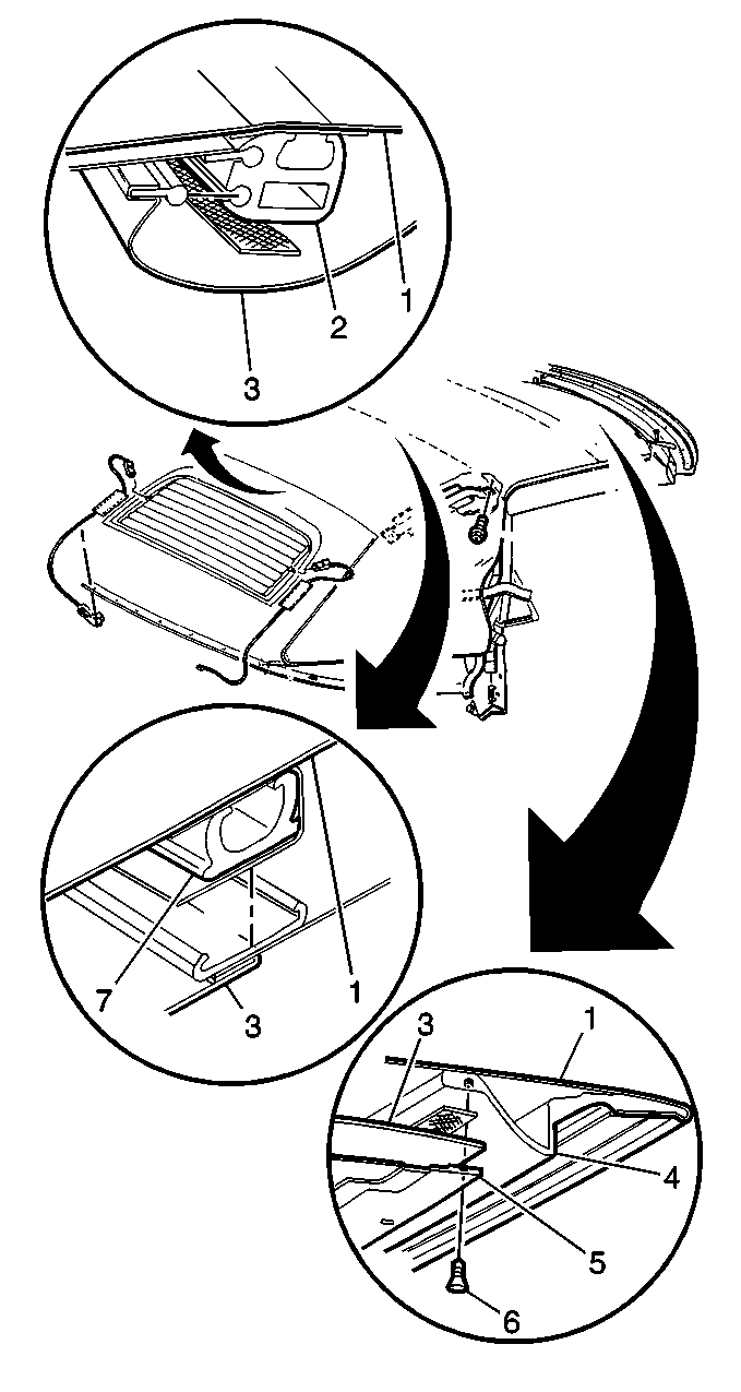
Use a 5/32 inch drill bit in order to drill out the rivets.
Use a 5/32 inch drill bit in order to drill out the rivets.
Installation Procedure
- Install the number 1 bow (8).
- Use CluberLube Microlube GL-261 or equivalent in order to lubricate the number 1 bushings (3) and bolts (2).
- Install the number 1 bow bushings (3) and the bolts (2).
- Install the number 1, 2, 3, and 4 bow position pad (10) to the number one bow (6).
- Install the side front stay rivets (8).
- Use black tape in order to cover the side front stay rivets (8).
- Install the cover to the number 1 bow (6).
- Install the front cover number 1 bow retainer (5).
- Install the front cover number 1 bow retainer bolts (4).
- Install the headlining trim finish panel (3) to the number 1 bow (4). Refer to Rear Quarter Trim Panel Replacement .
- Install the headlining trim finish panel rivets.
- Install the number 1 bow garnish molding (2).
- Install the number 1 bow garnish molding screws (3).
- Install the side rail garnish moldings. Refer to Windshield Pillar Garnish Molding Replacement .
- Turn the pump bypass valve fully counter-clockwise to the closed position.

Notice: Use the correct fastener in the correct location. Replacement fasteners must be the correct part number for that application. Fasteners requiring replacement or fasteners requiring the use of thread locking compound or sealant are identified in the service procedure. Do not use paints, lubricants, or corrosion inhibitors on fasteners or fastener joint surfaces unless specified. These coatings affect fastener torque and joint clamping force and may damage the fastener. Use the correct tightening sequence and specifications when installing fasteners in order to avoid damage to parts and systems.
Tighten
Tighten the bolts (2) to 17 N·m (13 lb ft).


Tighten
Tighten the bolts to 5 N·m (44 lb in).


Tighten
Tighten the bolts to 5 N·m (44 lb in).
Power Folding Top Bow Replacement Folding Top Number 2 Bow
Removal Procedure
- Remove the lower folding top to a suitable working position.
- Turn the pump bypass valve fully clockwise to the open position. Refer to Power Folding Top Operation .
- Remove the number 1 bow garnish molding bolts (3).
- Remove the number 1 garnish molding (2).
- Remove the bolts at each corner of the headlining trim finish panel (3).
- Peel the headlining trim finish panel (3) away from the adhesive in order to remove the headlining trim finish panel (3) from the number 1 bow (4).
- Remove the side rail garnish molding. Refer to Windshield Pillar Garnish Molding Replacement in Interior Trim.
- Remove the top cover from the number 1 bow (4).
- Remove the headlining trim finish panel from the number 2 bow (7).
- Peel the cover away from the adhesive in order to remove the cover (8) from the number 2 bow (7).
- Mark the location of the pad and staples.
- Remove the staples holding the number 1, 2, 3, and 4 bow position pad (10) to the number 2 bow (7).
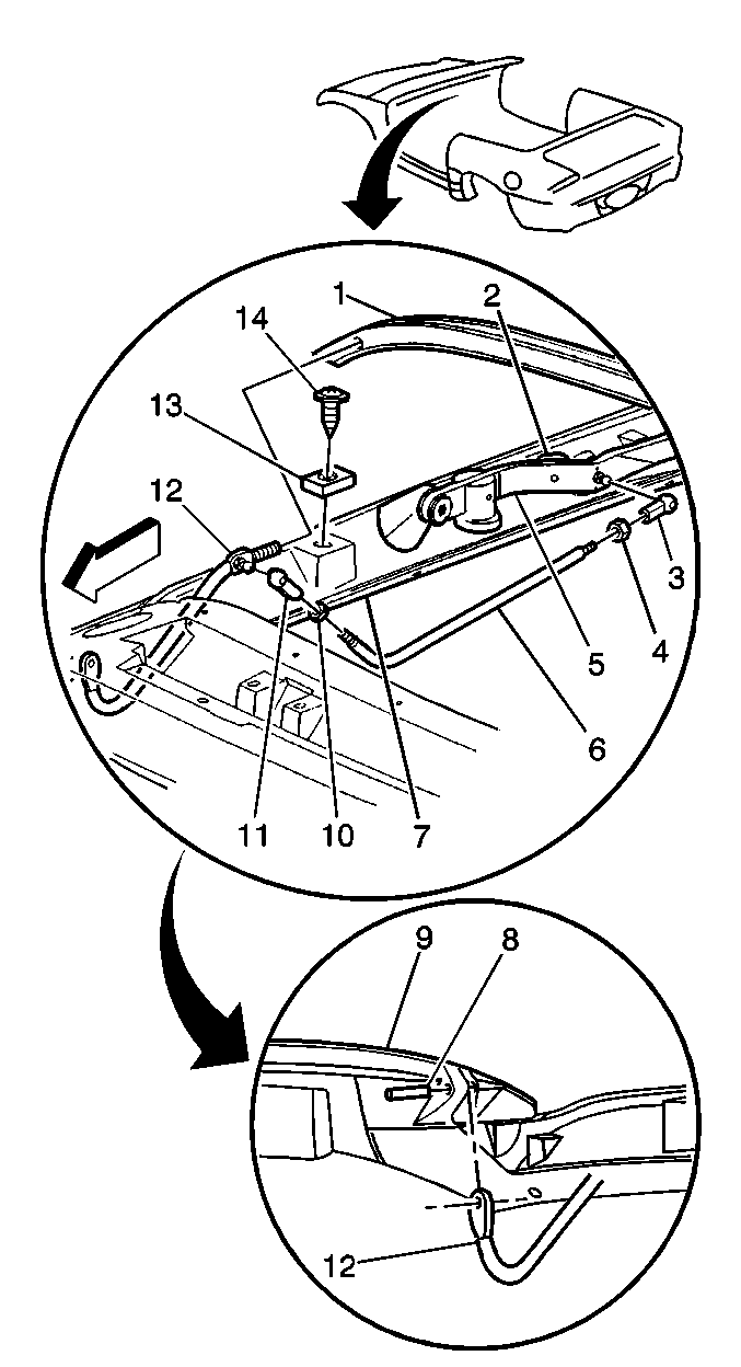
- Remove the number 1 bow links (12) from the number 1 bow (9) by punching out the pins.
- Remove the outside nut from the number 2 bow links (6).
- Remove the number 2 bow links (6) from the number 1 bow links (12).
- Remove the number 2 bow (1).
- Remove the old adhesive from the number 2 bow (1).


Pull the cover back along the cover retainer cable in order to reveal the number 2 bow.


Installation Procedure
- Apply tape to the number 2 bow (1).
- Install the number 2 bow (1).
- Install the number 2 bow links (6) to the number 1 bow links (12).
- Install the outside nut to the number two bow links (6).
- Install the number 1 bow links (12) to the number one bow (9).
- Install the pins.
- Install the 1,2,3, and 4 bow position pad (10) to their original positions on the number 2 bow (7).
- Install the cover (8) to the number 2 bow (7).
- Install the headlining trim finish panel to the number 2 bow (7). Refer to Rear Quarter Trim Panel Replacement .
- Install the top cover to the number 1 bow (6).
- Install the side rail garnish molding. Refer to Windshield Pillar Garnish Molding Replacement .
- Install the headlining trim finish panel (3) to the number one bow (4). Refer to Rear Quarter Trim Panel Replacement .
- Install the bolts at each corner of the headlining trim finish panel (3).
- Install the number 1 bow garnish molding (5).
- Install the number 1 bow garnish molding bolts (6).
- Turn the pump bypass valve fully counterclockwise to the closed position. Refer to Power Folding Top Operation .

Important: Use Hughes P/N HC- 4183, 3M© P/N 8046, or equivalent adhesive on the headliner or top cover attaching surfaces.

Install the staples at their original locations.
Wrap anti-ballooning strip around the bow.
Press the bow into place.

Power Folding Top Bow Replacement Folding Top Number 3 Bow
Removal Procedure
- Remove the lower folding top to a suitable working position.
- Turn the pump bypass valve fully clockwise to the open position. Refer to Power Folding Top Operation .
- Remove the top cover and headliner from the number 1, 2, and 3 bow.
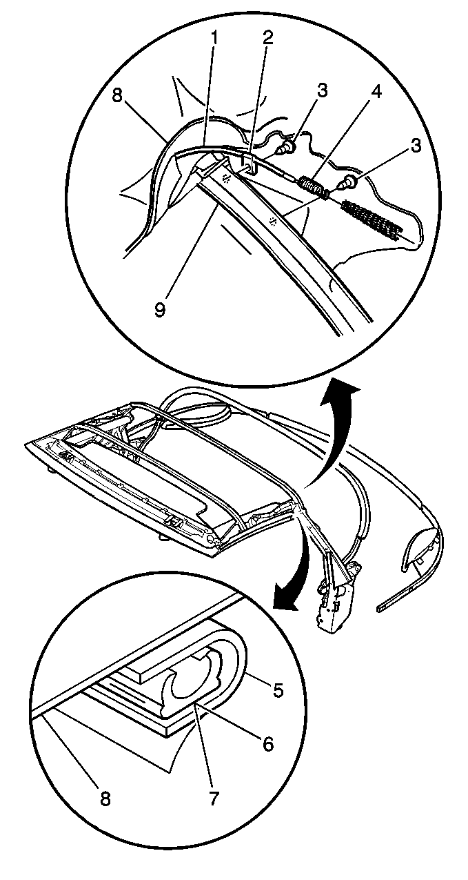
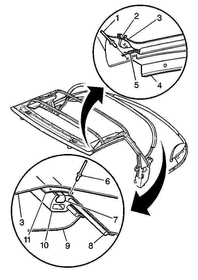
- Remove the cover retainer cable (1) from the outer arm (9).
- Remove the staples holding number 1, 2, 3, and 4 pad to the number 3 bow (2).
- Remove the bolts (1) from the number three bow (2).
- Reposition the plastic tackstrip along the channel in the number 3 bow (2) in order to reveal the bolts.
- Remove the number 3 bow (2).
- Remove the old tape from the number 3 bow (2).
- Remove the adhesive from the outer arm (7).

Mark the location of the pad and staples.
Installation Procedure
- Apply tape to the number 3 bow (2).
- Install the number 3 bow (2).
- Install the bolts (1) to the number 3 bow (2).
- Return the plastic tackstrip to the tackstrip's original position.
- Install the number 1, 2, 3, and 4 bow position pad to their original positions on the number 3 bow (6) and install the staples.
- Install the cover retainer cable (1) to the outer arm (9).
- Install the top cover and headliner to the number 1, 2, and 3 bow and outer arm.
- Turn the pump bypass valve fully counterclockwise to the closed position. Refer to Power Folding Top Operation .

Important: Use Hughes P/N HC-4183, 3M P/N 8046, or equivalent adhesive on the headliner or top cover attaching surfaces.
Notice: Use the correct fastener in the correct location. Replacement fasteners must be the correct part number for that application. Fasteners requiring replacement or fasteners requiring the use of thread locking compound or sealant are identified in the service procedure. Do not use paints, lubricants, or corrosion inhibitors on fasteners or fastener joint surfaces unless specified. These coatings affect fastener torque and joint clamping force and may damage the fastener. Use the correct tightening sequence and specifications when installing fasteners in order to avoid damage to parts and systems.
Tighten
Tighten the bolts (1) to 10 N·m (89 lb in).

Power Folding Top Bow Replacement Folding Top Number 4 Bow
Removal Procedure
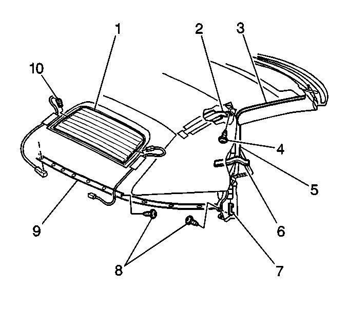
- Remove the bolts connecting the headlining trim finish panel elastic tension straps to the number 5 bow (4) and number 4 bow (1).
- Remove the rear retaining nuts from the number 5 bow (4).
- Remove the number 5 bow (4).
- Disconnect the electrical connectors from the rear window defogger.
- Remove the top cover in order to reveal the top of the number 4 bow (1) on both sides of the vehicle.
- Remove the hook-and-loop fastener pads on the number four bow (1).
- Mark the position of the number 4 and 5 bow position pad (3) on the number 4 bow (1).
- Remove the number 4 and 5 bow position pad (3) from the number 4 bow (1).
- Remove the lower end, inboard corner, of the number 4 and 5 bow position pad (3) in order to reveal the rear window.
- Mark the position of the number 1, 2, 3, and 4 bow position pad (10) at the number 4 bow position.
- Remove the number 1, 2, 3, and 4 bow position pad (10) from the number 4 bow (1).
- Mark the top edge of the number 5 bow (4) on the rear window fabric.
- Remove the center bolt for the rear window to the number 4 bolt (4).
- Slide out the rear window.
- Slide down the tackstrips on the number 4 bow (10) in order to reveal the top cover number four bow retainer (7).
- Use an appropriate tool in order to remove the top cover number 4 bow retainer (7).
- Remove the top cover (3) from the number 4 bow (10).
- Mark the ends of the number 4 bow (10) on the number 4 bow links.
- Remove the number 4 bow links bolts.
- Remove the number 4 bow (10) from the number 4 bow links.
- Slide the number 4 bow off the headlining trim finish panel (9).


Installation Procedure
- Slide the number 4 bow (10) over the headlining trim finish panel (9).
- Install the number 4 bow (10) to the original depth on the number 4 bow links.
- Install the bolts.
- Install the top cover (3) to the number 4 bow (10).
- Use an appropriate tool in order to install the top cover number 4 bow retainer.
- Return the tackstrips on the number 4 bow (10) to the original positions.
- Slide the rear window (8) into position.
- Install the center bolt for the rear window (8) to the number four bow (10).
- Install the number 1, 2, 3, and 4 bow position pad and staples to the original positions on the number 4 bow (10).
- Install the lower end of the number 4 and 5 bow position pad (3).
- Install the staples.
- Install the number 4 and 5 bow position pad (3).
- Install the staples to the original positions on the number 4 bow (1).
- Install the hook-and-loop fastener pads on the number 4 bow (1).
- Install the top cover to the original position.
- Connect the electrical connectors to the rear window defogger.
- Install the number 5 bow (4).
- Install the rear retaining nuts to the number 5 bow (4).
- Install the bolts connecting the headlining trim finish panel elastic tension straps to the number 4 bow (1) and number 5 bow (4).

Notice: Use the correct fastener in the correct location. Replacement fasteners must be the correct part number for that application. Fasteners requiring replacement or fasteners requiring the use of thread locking compound or sealant are identified in the service procedure. Do not use paints, lubricants, or corrosion inhibitors on fasteners or fastener joint surfaces unless specified. These coatings affect fastener torque and joint clamping force and may damage the fastener. Use the correct tightening sequence and specifications when installing fasteners in order to avoid damage to parts and systems.
Tighten
Tighten the bolts to 10 N·m (89 lb in).

Important: The number 4 bow uses the loop or soft portion of a hook-and-loop fastener tape in order to prevent the bow from showing through the top cover. The hook portion is not used. Loop tape is self-adhesive but must also be stapled to the bow. Failure to staple the tape into place could cause the tape to bunch up under the top cover.
Power Folding Top Bow Replacement Folding Top Number 5 Bow
Removal Procedure
- Turn the pump bypass valve fully clockwise to the open position. Refer to Power Folding Top Operation .
- Remove the bolts connecting the headlining trim finish panel elastic tension straps to the number 5 bow (44).
- Remove the rear retaining nuts from the number 5 bow (9).
- Raise the number 5 bow (9) over the top cover.
- Remove the staples attaching the number 5 bow (9) to the following components:
- Mark the position of the staples.
- Remove the number 5 bow (9).
| • | The attaching cover |
| • | The rear window (1) |
| • | The number 4 and 5 bow position pad |
Installation Procedure
- Install the following components to the number 5 bow (9) by stapling into the original positions:
- Install the number 5 bow (9) to the rear mounting studs.
- Install the rear retainer nuts to the number 5 bow mounting studs.
- Install the bolts connecting the headlining trim finish panel elastic tension strap to the number 5 bow (9).
- Turn the pump bypass valve fully counterclockwise to the closed position. Refer to Power Folding Top Operation .

| • | The number 4 and 5 bow position pad. |
| • | The rear window (1) |
| • | The cover |
