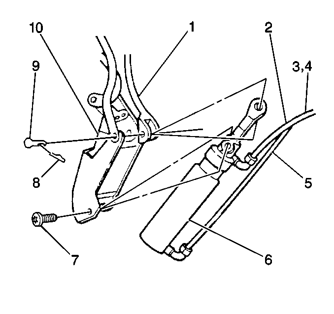
Removal Procedure
Each hose consists of 1 white and 1 pink hose bundled together. The upper hose controls the left cylinder. The lower hose control the right cylinder. The pink hoses attach to the top of each cylinder. The white hoses attach to the bottom of each cylinder.
Ensure the hoses remain connected as indicated. If the hoses are switched, 1 cylinder may extend while the other cylinder retracts. This will damage the folding top.
- Turn the pump bypass valve fully clockwise to the open position.
- Disconnect the battery negative cable.
- Remove the quarter inner rear trim finish panel. Refer to Quarter Inner Rear Trim Finish Panel Replacement in Body Rear End.
- Remove the rear speakers. Refer to Radio Rear Speaker Replacement in Entertainment.
- Remove the following components:
- Remove the cylinder (6) from the outer arm.
- Remove the cylinder bolt (7).
- Remove either the left cylinder upper hose (4) or the right lower hose (3) from the cylinder.
Important: When servicing the hydraulic system, leave the folding top raised and unattached from the windshield header in order to keep the cylinder rods extended and minimize fluid leakage.
Caution: Unless directed otherwise, the ignition and start switch must be in the OFF or LOCK position, and all electrical loads must be OFF before servicing any electrical component. Disconnect the negative battery cable to prevent an electrical spark should a tool or equipment come in contact with an exposed electrical terminal. Failure to follow these precautions may result in personal injury and/or damage to the vehicle or its components.

| • | The pivot bracket locking pin (8) |
| • | The cylinder pivot pin (9) |
Use a shop towel in order to control hydraulic oil leakage.
Installation Procedure
- Install either the left cylinder upper hose (4) or the right lower hose (3).
- Install the cylinder (6).
- Install the cylinder bolt (7).
- Install the cylinder (6) to the outer arm (1).
- Install the following components:
- Install the rear speaker. Refer to Radio Rear Speaker Replacement in Entertainment.
- Install the quarter inner rear trim finish panel. Refer to Quarter Inner Rear Trim Finish Panel Replacement in Body Rear End.
- Connect the battery negative cable.
- Raise the folding top.
- Turn the pump bypass valve fully counter-clockwise to the closed position.
- Bleed the hydraulic system.

Important: Replacement cylinders are supplied filled with oil. Do not remove the sealing caps from the cylinder until you are ready to connect the cylinder hose. Recommended fluid replacement is M-H5606 (natural color)
Notice: Use the correct fastener in the correct location. Replacement fasteners must be the correct part number for that application. Fasteners requiring replacement or fasteners requiring the use of thread locking compound or sealant are identified in the service procedure. Do not use paints, lubricants, or corrosion inhibitors on fasteners or fastener joint surfaces unless specified. These coatings affect fastener torque and joint clamping force and may damage the fastener. Use the correct tightening sequence and specifications when installing fasteners in order to avoid damage to parts and systems.
Tighten
Tighten the bolt to 5 N·m (44 lb in).
| • | The cylinder pivot pin (9) |
| • | The pivot bracket locking pin (8) |
Tighten
Tighten the cylinder hose fittings to 7 N·m (62 lb in).
Caution: Unless directed otherwise, the ignition and start switch must be in the OFF or LOCK position, and all electrical loads must be OFF before servicing any electrical component. Disconnect the negative battery cable to prevent an electrical spark should a tool or equipment come in contact with an exposed electrical terminal. Failure to follow these precautions may result in personal injury and/or damage to the vehicle or its components.
