Battery Positive Cable Replacement 3.8L Engine
Removal Procedure
- Remove the battery. Refer to Battery Replacement .
- Remove the positive cable from the fuseblock:
- Remove the positive cable cover from the cable.
- Remove the positive cable clips from the following:
- Remove the wiring harness ground bolt (at frame).
- Reposition the following:
- Remove the positive cable from the generator:
- Remove the positive cable clip from the engine lift bracket.
- Remove the positive cable clips from the cooling fans.
- Raise and suitably support the vehicle. Refer to Lifting and Jacking the Vehicle in General Information.
- Remove the positive cable from the engine mount stud:
- Remove the tie strap at the power steering line.
- Remove the starter motor shield. Refer to Starter Shield Replacement .
- Remove the positive cable from the starter solenoid:
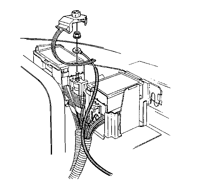
| 2.1. | Open the positive cable cap. |
| 2.2. | Remove the positive cable nut (at fuseblock). |
| 2.3. | Remove the positive cable from the stud. |
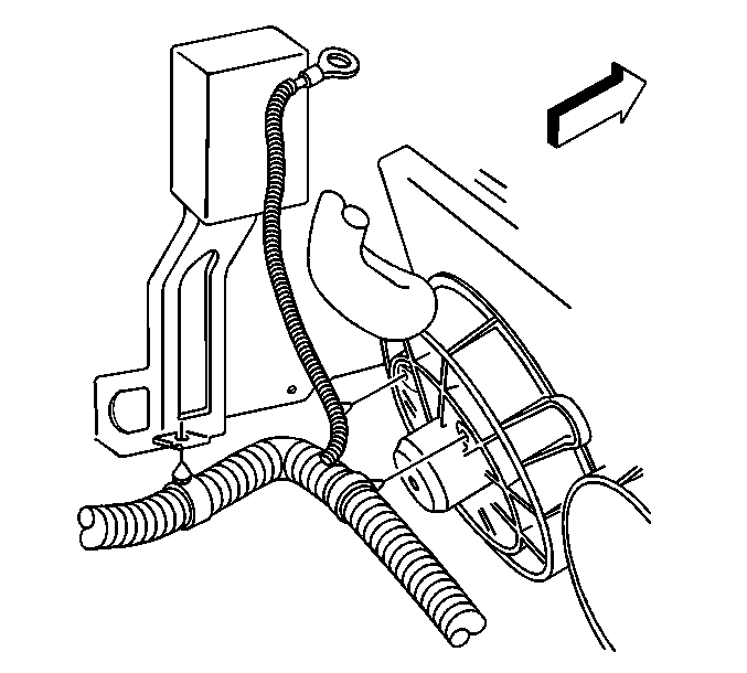
| • | Power steering reservoir bracket |
| • | Cooling fans |
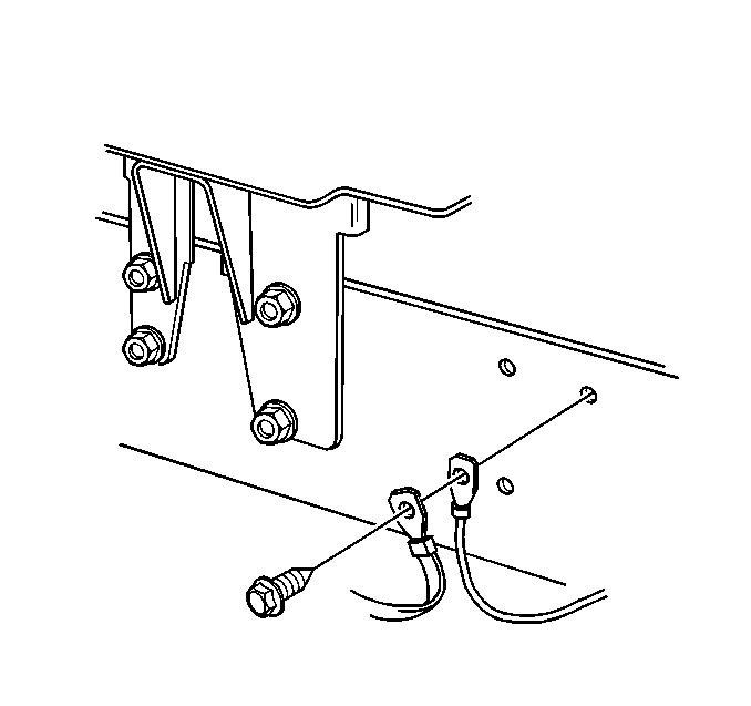
| • | Radio frequency (RF) ground strap |
| • | Cruise control ground lead |
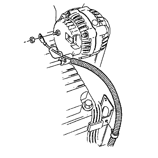
| • | Slide the boot back along the cable. |
| • | Remove the positive cable nut (at generator). |
| • | Remove the positive cable from the stud. |
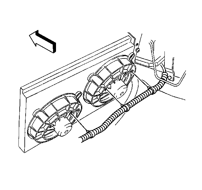

| • | Remove the positive cable nut. |
| • | Remove the harness clamp. |
| • | Remove the RF ground strap. |
| • | Remove the positive cable nut (at starter solenoid). |
| • | Remove the positive cable from the vehicle. |
Installation Procedure
- Install the positive cable to the vehicle.
- Install the positive cable nut (at starter solenoid).
- Install the starter motor shield. Refer to Starter Shield Replacement .
- Install the positive cable to the engine mount stud:
- Install a new tie strap around the cable and the power steering line.
- Position the following:
- Install the wiring harness ground bolt.
- Install the positive cable clips to the following:
- Lower the vehicle.
- Install the positive cable clips at the cooling fans.
- Install the positive cable clip to the engine lift bracket.
- Install the positive cable to the generator:
- Install the positive cable cover to the cable.
- Install the positive cable to the stud on the fuseblock:
- Install the battery. Refer to Battery Replacement .

Notice: Use the correct fastener in the correct location. Replacement fasteners must be the correct part number for that application. Fasteners requiring replacement or fasteners requiring the use of thread locking compound or sealant are identified in the service procedure. Do not use paints, lubricants, or corrosion inhibitors on fasteners or fastener joint surfaces unless specified. These coatings affect fastener torque and joint clamping force and may damage the fastener. Use the correct tightening sequence and specifications when installing fasteners in order to avoid damage to parts and systems.
Tighten
Tighten the positive cable nut (at starter solenoid) to 10 N·m
(89 lb in).
| • | Install the RF ground strap. |
| • | Install the harness clamp. |
| • | Install the positive cable nut. |
Tighten
Tighten the positive cable nut to 25 N·m (18 lb ft).

| • | RF ground strap |
| • | Cruise control ground lead |
Tighten
Tighten the wiring harness ground bolt to 12 N·m (106 lb in).

| • | Power steering reservoir bracket |
| • | Cooling fans |


| 12.1. | Install the positive cable to the stud. |
| 12.2. | Install the positive cable nut (at generator). |
Tighten
Tighten the positive cable nut (at generator) to 22 N·m
(16 lb ft).
| 12.3. | Slide the boot over the generator stud. |

| • | Install the positive cable to the stud. |
| • | Install the positive cable nut (at fuseblock). |
Tighten
Tighten the positive cable nut (at fuseblock) to 14 N·m
(10 lb ft).
| • | Close the positive cable cap. |
Battery Positive Cable Replacement 5.7L Engine
Removal Procedure
- Remove the battery. Refer to Battery Replacement .
- Remove the positive cable from the fuseblock:
- Remove the positive cable cover from the cable.
- Raise and suitably support the vehicle. Refer to Lifting and Jacking the Vehicle in General Information.
- Remove the positive cable clips at the cooling fans.
- Remove the wiring harness ground bolt (at frame).
- Reposition the following:
- Remove the positive cable from the generator:
- Remove the positive cable from the starter solenoid:

| 2.1. | Open the positive cable cap. |
| 2.2. | Remove the positive cable nut (at fuseblock). |
| 2.3. | Remove the positive cable from the stud. |
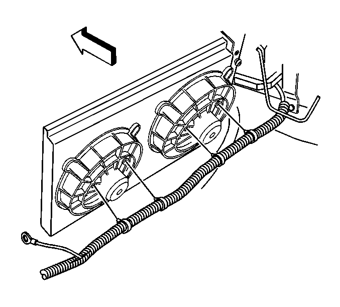

| • | Radio frequency (RF) ground strap |
| • | Cruise control ground lead |
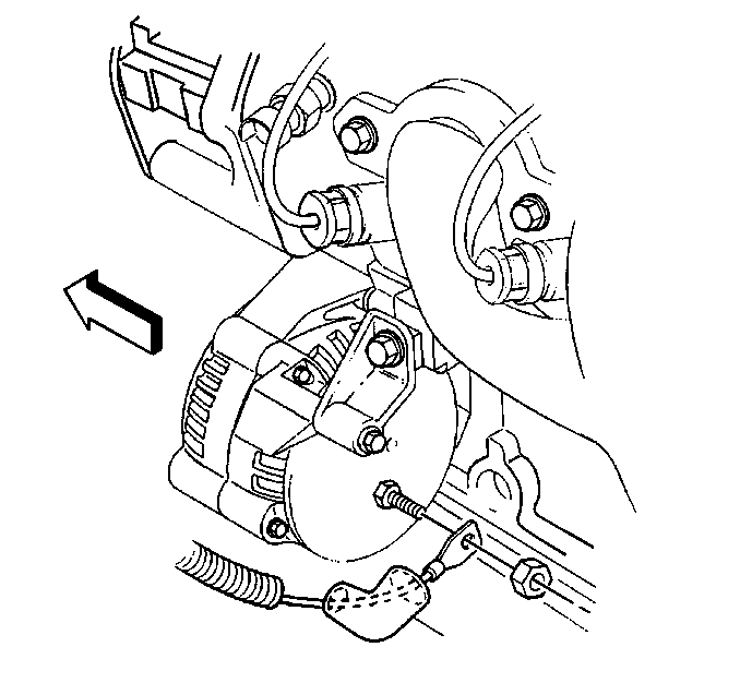
| • | Slide the boot back along the cable. |
| • | Remove the positive cable nut (at generator). |
| • | Remove the positive cable from the stud. |

| • | Remove the positive cable nut (3) (at starter solenoid). |
| • | Remove the positive cable from the harness conduit. |
Installation Procedure
- Install the positive cable to the harness conduit.
- Install the positive cable nut (3) (at starter solenoid).
- Install the positive cable to the generator:
- Position the following:
- Install the wiring harness ground bolt.
- Install the positive cable clips at the cooling fans.
- Lower the vehicle.
- Install the positive cable cover to the cable.
- Install the positive cable to the stud on the fuseblock:
- Install the battery. Refer to Battery Replacement .

Notice: Use the correct fastener in the correct location. Replacement fasteners must be the correct part number for that application. Fasteners requiring replacement or fasteners requiring the use of thread locking compound or sealant are identified in the service procedure. Do not use paints, lubricants, or corrosion inhibitors on fasteners or fastener joint surfaces unless specified. These coatings affect fastener torque and joint clamping force and may damage the fastener. Use the correct tightening sequence and specifications when installing fasteners in order to avoid damage to parts and systems.
Tighten
Tighten the positive cable nut (at starter solenoid) to 10 N·m
(89 lb in).

| • | Install the positive cable to the stud. |
| • | Install the positive cable nut (at generator). |
Tighten
Tighten the positive cable nut (at generator) to 22 N·m
(16 lb ft).
| • | Slide the boot over the generator stud. |

| • | RF ground strap |
| • | Cruise control ground lead |
Tighten
Tighten the wiring harness ground bolt to 12 N·m (106 lb in).
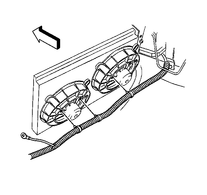

| • | Install the positive cable to the stud. |
| • | Install the positive cable nut (at fuseblock). |
Tighten
Tighten the positive cable nut (at fuseblock) to 14 N·m
(10 lb ft).
| • | Close the positive cable cap. |
