Removal Procedure
Notice: The vehicle's wheels must be in a straight-ahead position and the key must be in a LOCK position when removing or installing the steering column. Failure to do so may cause the SIR coil assembly to become uncentered and may result in unneeded SIR system repairs.
Notice: When the steering column is removed from the vehicle, it is extremely susceptible to damage. Dropping the column on its end could collapse the steering shaft or loosen plastic injections that keep the column rigid. Leaning on the column could cause steering column jacket to bend or deform. Any of the above conditions could impair column assembly's collapsible design. If the steering wheel must be removed, use only the specified steering wheel puller and steering wheel puller bolts. Never hammer on the end of the steering shaft because hammering could loosen plastic injections that keep the column right.
- Remove the left instrument panel insulator.
- Remove the instrument panel driver knee bolster and deflector.
- Disable the SIR system.
- Remove the steering wheel, if the column is to be replaced. Refer to Steering Wheel Replacement .
- Remove the intermediate steering shaft bolt from the steering gear coupling shaft and column.
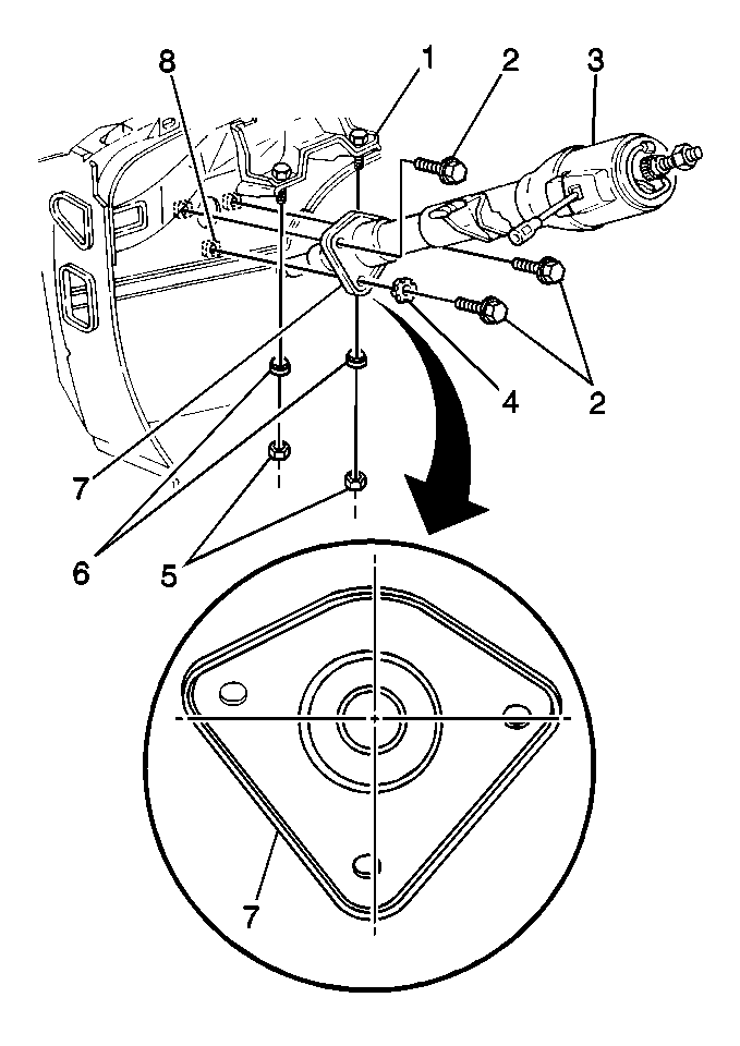
- Remove the bolts (2) that attach the cover (7) to the dash panel.
- Remove the cover (7) from the dash panel.
- Disconnect the electrical connectors.
- Remove the nuts (5) and shims (6) from the steering column support.
- Remove the automatic transmission park lock cable from the ignition switch, if equipped.
- Remove the column (3) from the vehicle.

Installation Procedure
Notice: If a service replacement steering column is being installed, do not remove the antirotation pin until after the column has been connected to the steering gear. Removing the antirotation pin before the column is connected to the steering gear may damage the SIR coil.
- Position the column (3) into the vehicle.
- Install the automatic transmission park lock cable to the ignition switch, if equipped. Refer to Automatic Transmission, On-Vehicle Service.
- Install the shims (6) and the nuts (5) to the steering column support.
- Install the intermediate steering shaft bolt to the steering gear coupling shaft. Refer to Steering Gear Coupling Shaft.
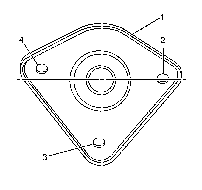
- Install the cover to the dash. Install the bolt in the following order:
- Position the cover to the dash panel.
- Connect the electrical connectors.
- Install the dash panel bolts.
- Install the steering wheel, if column is replaced. Refer to Steering Wheel Replacement .
- Enable the SIR system.
- Install the instrument panel driver knee bolster and deflector.
- Install the left instrument panel insulator.

Notice: Use the correct fastener in the correct location. Replacement fasteners must be the correct part number for that application. Fasteners requiring replacement or fasteners requiring the use of thread locking compound or sealant are identified in the service procedure. Do not use paints, lubricants, or corrosion inhibitors on fasteners or fastener joint surfaces unless specified. These coatings affect fastener torque and joint clamping force and may damage the fastener. Use the correct tightening sequence and specifications when installing fasteners in order to avoid damage to parts and systems.
Tighten
Tighten the steering column support nuts to 25 N·m (18 lb ft).

| 5.1. | Install the lower (3) bolt. |
| 5.2. | Install the outboard (4) bolt. |
| 5.3. | Install the inboard (2) bolt. |
Tighten
Tighten the dash panel bolts to 18 N·m (14 lb ft).
