Cruise Control Inoperative/Malfunctioning W/O ETC
Diagnostic Aids
Important: Perform the following in order to avoid misdiagnosis:
• Inspect for proper operation of the brake lamps. • Inspect the throttle linkage for mechanical binding which could
cause the system to malfunction. • Inspect the cruise control adjustment for minimum slack. • Inspect for stored Diagnostic Trouble Codes DTC's in the PCM.
Refer to
Powertrain On Board Diagnostic (OBD) System Check
-- 3.8L or
Powertrain On Board Diagnostic (OBD) System Check
-- 5.7L in
Engine Controls. • EMI on the speed sensor signal circuit may cause erratic cruise
control operation.
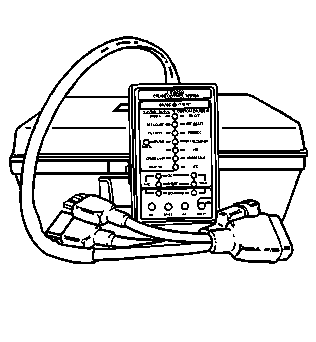
Alternative Diagnosis
The J 42958 Cruise Control Tester may be used if desired. See Service Bulletin 83-90-08A or refer to Cruise Control Inoperative/Malfunctioning Using J 42958 Cruise Control Tester
Conditions for Enabling Cruise Control
| • | The vehicle speed is more than 40 km/h (25 mph) |
| • | PARK, REVERSE, NEUTRAL, or 1st gear IS NOT indicated by the Park / Neutral Position Switch. |
| • | An over / undercharged battery condition DOES NOT exist. |
| • | Normal engine RPM is present. |
| • | High engine RPM (fuel cut-off) is not present. Refer to Fuel Metering Modes of Operation -- 3.8L or Fuel Metering Modes of Operation -- 5.7L in Engine Controls. |
Step | Action | Value(s) | Yes | No |
|---|---|---|---|---|
1 | Did you review the system operation and perform the necessary inspections? | -- | Go to Step 2 | |
2 |
Does the test lamp illuminate? | -- | Go to Step 3 | Go to Step 36 |
3 | Probe the ignition positive voltage circuit of the cruise control module with a test lamp that is connected to the ground circuit of the cruise control module. Refer to Circuit Testing in Wiring Systems. Does the test lamp illuminate? | -- | Go to Step 4 | Go to Step 37 |
4 |
Does the test lamp illuminate on any of the circuits? | -- | Go to Step 16 | Go to Step 5 |
5 |
Does the test lamp illuminate? | -- | Go to Step 6 | Go to Step 17 |
6 |
Does the test lamp illuminate? | -- | Go to Step 7 | Go to Step 19 |
7 |
Does the test lamp illuminate? | -- | Go to Step 8 | Go to Step 20 |
8 | Probe the cruise cancel circuit with a test lamp that is connected to a good ground. Refer to Circuit Testing in Wiring Systems. Does the test lamp illuminate? | -- | Go to Step 9 | Go to Step 21 |
9 | Depress the brake pedal while monitoring the test lamp. Does the test lamp illuminate? | -- | Go to Step 22 | Go to Step 10 |
10 | Probe the brake input circuit with a test lamp that is connected to a good ground. Refer to Circuit Testing in Wiring Systems. Does the test lamp illuminate? | -- | Go to Step 23 | Go to Step 11 |
11 | Depress the brake pedal while monitoring the test lamp. Does the test lamp illuminate? | -- | Go to Step 12 | Go to Step 24 |
12 | Probe the cruise disable/enable circuit with a test lamp that is connected to battery voltage. Refer to Circuit Testing in Wiring Systems. Does the test lamp illuminate? | -- | Go to Step 25 | Go to Step 13 |
13 | Use a scan tool in order to command the cruise inhibit/enable OFF. Does the test lamp illuminate? | -- | Go to Step 14 | Go to Step 26 |
14 | Probe the cruise engaged output circuit with a DMM that is connected to a good ground. Refer to Circuit Testing in Wiring Systems. Does the voltage measure near the specified value? | B+ | Go to Step 15 | Go to Step 27 |
15 |
Does the voltage displayed on the scan tool vary? | -- | Go to Step 35 | Go to Step 28 |
16 | Test the circuit that illuminated the test lamp for a short to voltage. Refer to Circuit Testing and Wiring Repairs in Wiring Systems. Did you find and correct the condition? | -- | Go to Step 43 | Go to Step 34 |
17 | Test the on/off circuit for an open or a high resistance. Refer to Circuit Testing and Wiring Repairs in Wiring Systems. Did you find and correct the condition? | -- | Go to Step 43 | Go to Step 18 |
18 | Test the ignition positive voltage circuit for an open or high resistance between the cruise control module and the cruise control switch. Refer to Circuit Testing and Wiring Repairs in Wiring Systems. Did you find and correct the condition? | -- | Go to Step 43 | Go to Step 34 |
19 | Test the set/coast circuit for an open or a high resistance. Refer to Circuit Testing and Wiring Repairs in Wiring Systems. Did you find and correct the condition? | -- | Go to Step 43 | Go to Step 34 |
20 | Test the resume/accelerate circuit for an open or a high resistance. Refer to Circuit Testing and Wiring Repairs in Wiring Systems. Did you find and correct the condition? | -- | Go to Step 43 | Go to Step 34 |
21 | Test the cruise cancel circuit for an open or a high resistance. Refer to Circuit Testing and Wiring Repairs in Wiring Systems. Did you find and correct the condition? | -- | Go to Step 43 | Go to Step 29 |
22 | Test the cruise cancel circuit for a short to voltage. Refer to Circuit Testing and Wiring Repairs in Wiring Systems. Did you find and correct the condition? | -- | Go to Step 43 | Go to Step 29 |
23 | Test the brake input circuit for a short to voltage. Refer to Circuit Testing and Wiring Repairs in Wiring Systems. Did you find and correct the condition? | -- | Go to Step 43 | Go to Step 30 |
24 | Test the brake input circuit for an open or a high resistance. Refer to Circuit Testing and Wiring Repairs in Wiring Systems. Did you find and correct the condition? | -- | Go to Step 43 | Go to Step 30 |
25 | Test the cruise disable/enable circuit for a short to ground. Refer to Circuit Testing and Wiring Repairs in Wiring Systems. Did you find and correct the condition? | -- | Go to Step 43 | Go to Step 33 |
26 | Test the cruise disable/enable circuit for an open, a high resistance, or a short to voltage. Refer to Circuit Testing and Wiring Repairs in Wiring Systems. Did you find and correct the condition? | -- | Go to Step 43 | Go to Step 33 |
27 | Test the cruise engaged output circuit for an open, a high resistance, or a short to voltage. Refer to Circuit Testing and Wiring Repairs in Wiring Systems. Did you find and correct the condition? | -- | Go to Step 43 | Go to Step 33 |
28 | Test the speed sensor circuit for an open or a high resistance. Refer to Circuit Testing and Wiring Repairs in Wiring Systems. Did you find and correct the condition? | -- | Go to Step 43 | Go to Step 33 |
29 | Inspect the cruise control release (brake) switch and cruise control clutch switch for proper adjustment. Did you find and correct the condition? | -- | Go to Step 43 | Go to Step 31 |
30 | Inspect the stoplamp switch for proper adjustment. Refer to Stop Lamp Switch Adjustment in Hydraulic Brakes. Did you find and correct the condition? | -- | Go to Step 43 | Go to Step 32 |
31 | Inspect for poor connections at the harness connector of the cruise control release (brake) switch and the cruise control (clutch) switch. Refer to Testing for Intermittent Conditions and Poor Connections and Connector Repairs in Wiring Systems. Did you find and correct the condition? | -- | Go to Step 43 | Go to Step 38 |
32 | Inspect for poor connections at the harness connector of the stoplamp switch. Refer to Testing for Intermittent Conditions and Poor Connections and Connector Repairs in Wiring Systems. Did you find and correct the condition? | -- | Go to Step 43 | Go to Step 39 |
33 | Inspect for poor connections at the harness connector of the PCM. Refer to Testing for Intermittent Conditions and Poor Connections and Connector Repairs in Wiring Systems. Did you find and correct the condition? | -- | Go to Step 43 | Go to Step 40 |
34 | Inspect for poor connections at the harness connector of the cruise control switch. Refer to Testing for Intermittent Conditions and Poor Connections and Connector Repairs in Wiring Systems. Did you find and correct the condition? | -- | Go to Step 43 | Go to Step 41 |
35 | Inspect for poor connections at the harness connector of the cruise control module. Refer to Testing for Intermittent Conditions and Poor Connections and Connector Repairs in Wiring Systems. Did you find and correct the condition? | -- | Go to Step 43 | Go to Step 42 |
36 | Repair the ignition positive voltage circuit of the cruise control module. Refer to Wiring Repairs in Wiring Systems. Did you complete the repair? | -- | Go to Step 43 | -- |
37 | Repair the ground circuit of the cruise control module. Refer to Wiring Repairs in Wiring Systems. Did you complete the repair? | -- | Go to Step 43 | -- |
38 | Replace the cruise control release (brake) switch or the cruise control (clutch) switch. Refer to Cruise Control Release Switch Replacement . Did you complete the replacement? | -- | Go to Step 43 | -- |
39 | Replace the stoplamp switch. Refer to Stop Lamp Switch Replacement in Hydraulic Brakes. Did you complete the replacement? | -- | Go to Step 43 | -- |
40 | Replace the PCM. Refer to Powertrain Control Module Replacement/Programming - 3.8L or Powertrain Control Module Replacement/Programming - 5.7L in Engine Controls. Did you complete the replacement? | -- | Go to Step 43 | -- |
41 | Replace the cruise control switch. Refer to Multifunction Turn Signal Lever Replacement - On Vehicle in Steering Wheel and Column - Tilt. Did you complete the replacement? | -- | Go to Step 43 | -- |
42 | Replace the cruise control module. Refer to Cruise Control Module Replacement . Did you complete the replacement? | -- | Go to Step 43 | -- |
43 | Operate the vehicle within the conditions for cruise control operation. Does the cruise control system operate correctly? | -- | System OK | Go to Step 2 |
Cruise Control Inoperative/Malfunctioning W/ETC
Diagnostic Aids
Important: Perform the following in order to avoid misdiagnosis.
• Inspect for proper operation of brake lamps and clutch switch,
if equipped. • EMI on the speed sensor signal circuit may cause erratic cruise
control operation.
Conditions for Enabling Cruise Control
The vehicle speed is greater than 40 km/h (25 mph).
Step | Action | Yes | No |
|---|---|---|---|
Schematic Reference: Cruise Control Schematics | |||
1 | Did you perform A Diagnostic System Check - Cruise Control? | Go to Step 2 | |
2 |
Did the scan tool parameter change state? | Go to Step 3 | Go to Step 9 |
3 |
Did the cruise control Set/Coast parameter change state? | Go to Step 4 | Go to Step 14 |
4 |
Did the cruise control Resume Accelerate parameter change state? | Go to Step 5 | Go to Step 15 |
5 |
Did the stop lamp switch parameter change state? | Go to Step 6 | Go to Step 10 |
6 |
Did the cruise release switch parameter change state? | Go to Step 7 | Go to Step 11 |
7 | Is the vehicle equipped with a manual transmission? | Go to Step 8 | Go to Step 29 |
8 |
Did the CPP switch parameter change state? | Go to Step 29 | Go to Step 12 |
9 |
Did the test lamp illuminate? | Go to Step 13 | Go to Step 21 |
10 |
Did the test lamp illuminate? | Go to Step 16 | Go to Step 22 |
11 |
Did the test lamp illuminate? | Go to Step 18 | Go to Step 23 |
12 |
Did the test lamp illuminate? | Go to Step 20 | Go to Step 24 |
13 | Test the cruise control ON switch signal circuit for a open, high resistance, short to ground or short to voltage. Refer to Circuit Testing and Wiring Repairs in Wiring Systems. Did you find and correct the condition? | Go to Step 35 | Go to Step 28 |
14 | Test the cruise control Set/Coast signal circuit for a open, high resistance, short to ground or short to voltage. Refer to Circuit Testing and Wiring Repairs in Wiring Systems. Did you find and correct the condition? | Go to Step 35 | Go to Step 28 |
15 | Test the cruise control Resume/Accelerate signal circuit for a open, high resistance, short to ground or short to voltage. Refer to Circuit Testing and Wiring Repairs in Wiring Systems. Did you find and correct the condition? | Go to Step 35 | Go to Step 28 |
16 | Test the stop lamp switch signal circuit for a open, high resistance, short to ground or short to voltage. Refer to Circuit Testing and Wiring Repairs in Wiring Systems. Did you find and correct the condition? | Go to Step 35 | Go to Step 17 |
17 | Check the stop lamp switch for proper adjustment. Refer to Stop Lamp Switch Adjustment in Hydraulic Brakes. Did you find and correct the condition? | Go to Step 35 | Go to Step 25 |
18 | Test the cruise release switch signal circuit for a open, high resistance, short to ground or short to voltage. Refer to Circuit Testing and Wiring Repairs in Wiring Systems. Did you find and correct the condition? | Go to Step 35 | Go to Step 19 |
19 | Check the cruise release switch for proper adjustment. Refer to Cruise Control Cable Adjustment in Hydraulic Brakes. Did you find and correct the condition? | Go to Step 35 | Go to Step 26 |
20 | Test the CPP switch signal circuit for a open, high resistance, short to ground or short to voltage. Refer to Circuit Testing and Wiring Repairs in Wiring Systems. Did you find and correct the condition? | Go to Step 35 | Go to Step 27 |
21 | Repair the open, high resistance or short to ground in the multifunction turn signal lever ignition positive voltage feed circuit. Refer to Wiring Repairs in Wiring Systems. Did you complete the repair? | Go to Step 35 | -- |
22 | Repair the open, high resistance or short to ground in the stop lamp switch battery positive voltage feed circuit. Refer to Wiring Repairs in Wiring Systems. Did you complete the repair? | Go to Step 35 | -- |
23 | Repair the open, high resistance or short to ground in the cruise release switch battery positive voltage feed circuit. Refer to Wiring Repairs in Wiring Systems. Did you complete the repair? | Go to Step 35 | -- |
24 | Repair the open, high resistance or short to ground in the CPP switch battery positive voltage feed circuit. Refer to Wiring Repairs in Wiring Systems. Did you complete the repair? | Go to Step 35 | -- |
25 | Inspect for poor connections at the harness connector of the stop lamp switch. Refer to Testing for Intermittent Conditions and Poor Connections and Connector Repairs in Wiring Systems. Did you find and correct the condition? | Go to Step 35 | Go to Step 30 |
26 | Inspect for poor connections at the harness connector of the cruise release switch. Refer to Testing for Intermittent Conditions and Poor Connections and Connector Repairs in Wiring Systems. Did you find and correct the condition? | Go to Step 35 | Go to Step 31 |
27 | Inspect for poor connections at the harness connector of the CPP switch. Refer to Testing for Intermittent Conditions and Poor Connections and Connector Repairs in Wiring Systems. Did you find and correct the condition? | Go to Step 35 | Go to Step 32 |
28 | Inspect for poor connections at the harness connector of the multifunction turn signal lever. Refer to Testing for Intermittent Conditions and Poor Connections and Connector Repairs in Wiring Systems. Did you find and correct the condition? | Go to Step 35 | Go to Step 33 |
29 | Inspect for poor connections at the harness connector of the PCM. Refer to Testing for Intermittent Conditions and Poor Connections and Connector Repairs in Wiring Systems. Did you find and correct the condition? | Go to Step 35 | Go to Step 34 |
30 | Replace the stop lamp switch. Refer to Stop Lamp Switch Replacement in Hydraulic Brakes. Did you complete the repair. | Go to Step 35 | -- |
31 | Replace the cruise release switch. Refer to Cruise Control Release Switch Replacement . Did you complete the repair. | Go to Step 35 | -- |
32 | Replace the CPP switch. Refer to Clutch Pedal Position Switch Replacement in Clutch. Did you complete the repair. | Go to Step 35 | -- |
33 | Replace the multifunction turn signal lever. Refer to Multifunction Turn Signal Lever Replacement - On Vehicle in Steering Wheel and Column - Tilt. Did you complete the repair? | Go to Step 35 | -- |
34 |
Important: The PCM must be reprogrammed before replacement. Replace the PCM. Refer to Powertrain Control Module Replacement/Programming in Engine Controls. | Go to Step 35 | -- |
35 | Operate the vehicle with in the conditions for cruise control operation. Does the cruise control system operate properly? | System OK | Go to Step 2 |
