Removal Procedure
- Disable the supplemental inflatable restraint (SIR) system. Refer to Disabling the SIR System in SIR.
- Remove the left side instrument panel insulator. Refer to Instrument Panel Insulator Panel Replacement - Left Side in Instrument Panel, Gauges and Console.
- Remove the instrument panel driver knee bolster and deflector. Refer to Driver Knee Bolster Replacement in Instrument Panel, Gauges and Console.
- Remove the front floor console. Refer to Front Floor Console Replacement in Instrument Panel, Gauges and Console.
- Remove the body hinge pillar trim panel. Refer to Body Hinge Pillar Trim Panel Replacement in Interior Trim.
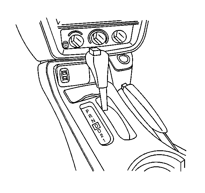
- Place the transmission control into the PARK position.
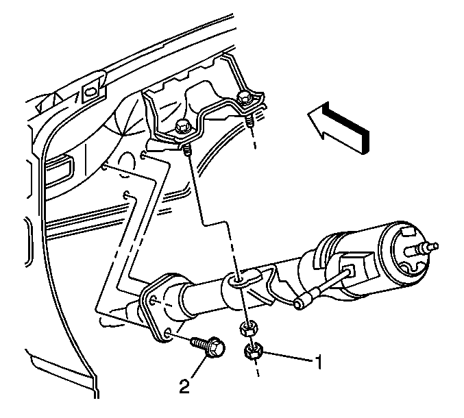
- Remove the steering column mounting bolts (2).
- Remove the steering column mounting nuts (1).
- Lower the steering column.
- Reposition the floor carpet until the retaining clip on the tunnel is accessible.
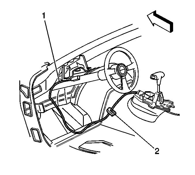
- Open the retaining clip (2) on the driver side of the tunnel and remove the park lock cable (1).
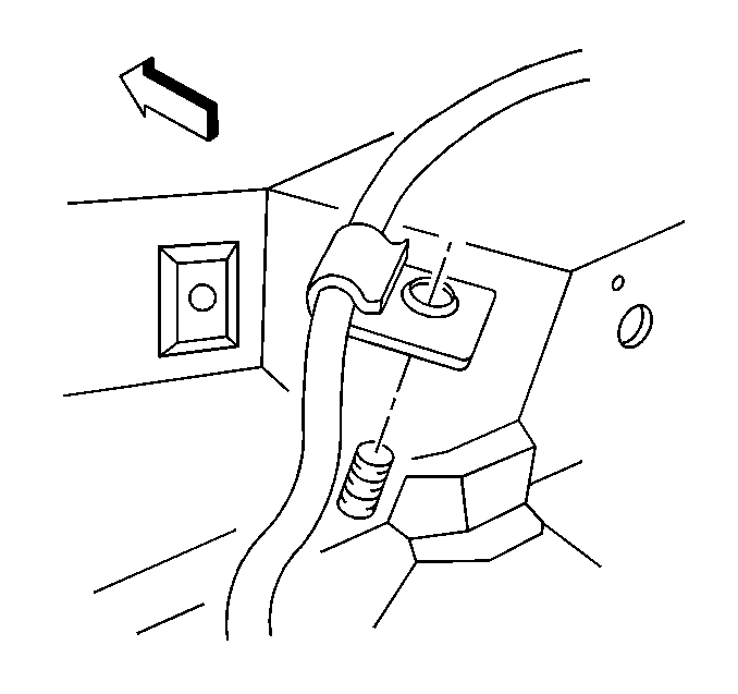
- Remove the park lock cable clip from the stud on the front of dash.
- Turn the ignition key to the RUN (4) position.
- Release the park lock cable from the inhibitor attached to the steering column.
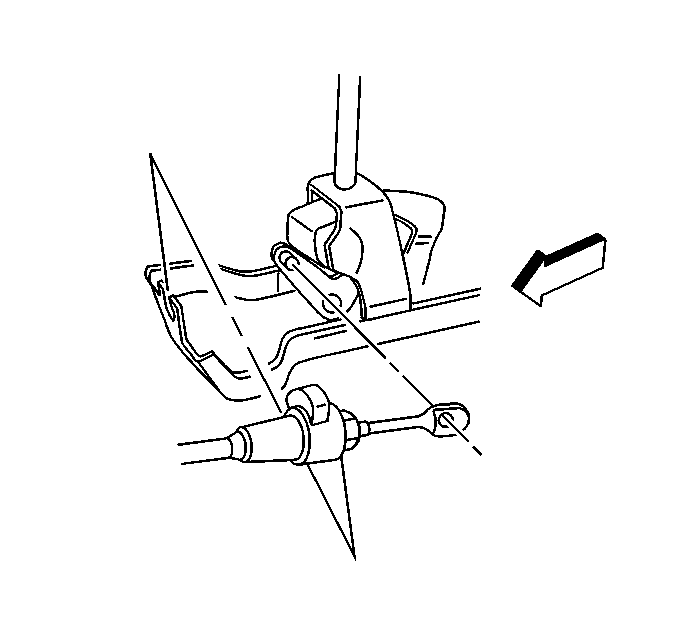
- Disconnect the park lock cable from the control lever pin.
- Remove the park lock cable from the transmission control base.
- Remove the park lock cable from the vehicle.
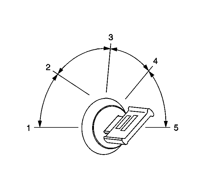
Important: Do not proceed to the next step with the ignition key in any other position.
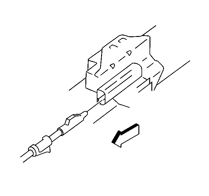
| 14.1. | Insert a small flat bladed screwdriver into the inhibitor slot. |
| 14.2. | Depress the park lock cable latch. |
| 14.3. | Gently pull the park lock cable from the inhibitor. |
Installation Procedure
- Install the park lock cable to the vehicle.
- Place the transmission control into the PARK position.
- Snap the cable connector lock button (1) to the UP position.
- Install the park lock cable to the transmission control base.
- Turn the ignition key to the RUN (4) position.
- Snap the park lock cable into the inhibitor on the steering column.
- Turn the ignition key to the LOCK position.
- Connect the park lock cable to the control lever pin.
- Push the cable connector forward in order to remove slack.
- With no load applied to the connector nose, snap the cable connector lock button (1) down.
- Install the park lock cable clip to the stud on the front of dash.
- Install the park lock cable (1) to the retaining clip (2) on the driver side of the tunnel. Close the clip.
- Reinstall the floor carpet.
- Raise the steering column.
- Install the shim to the outboard bracket stud.
- Finger start the steering column mounting nuts (1).
- Install the steering column mounting bolts (2).
- Install the front floor console. Refer to Front Floor Console Replacement in Instrument Panel, Gauges, and Console.
- Install the instrument panel driver knee bolster and deflector. Refer to Driver Knee Bolster Replacement in Instrument Panel, Gauges, and Console.
- Install the left side instrument panel insulator. Refer to Instrument Panel Insulator Panel Replacement - Left Side in Instrument Panel, Gauges, and Console.
- Enable the SIR system. Refer to Enabling the SIR System in SIR.

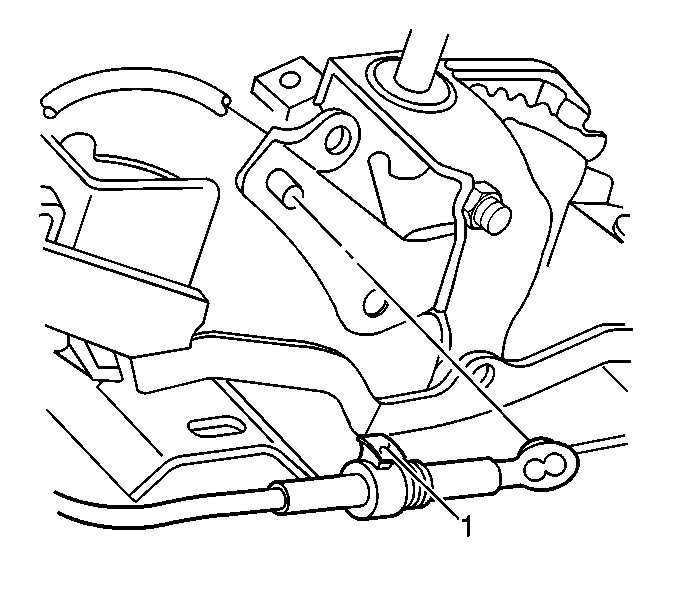


Important: Do not proceed to the next step with the ignition key in any other position.


Caution: In order to ensure the intended function of the steering
column in a vehicle during a crash and in order to avoid personal injury to
the driver, perform the following:
• Tighten the steering column lower fasteners before you tighten
the steering column upper fasteners. Failure to do this can damage the steering
column. • Tighten the steering column fasteners to the specified torque.
Overtightening the upper steering column fasteners could affect the steering
column collapse.
Tighten
Tighten the steering column mounting nuts (1) and bolts (2) to 10 N·m
(89 lb in).
Functional Operation
- Place the transmission control in the PARK position.
- Turn the ignition key to the LOCK position (2).
- Transmission control should not be able to be moved to another position.
- The ignition key should be able to be removed from the ignition.
- Turn the ignition key to the RUN position.
- Place the transmission control in the NEUTRAL position.
- The ignition key should not be able to be removed from the ignition.
- If the above functional checks were met, the adjustment is complete.
- If the ignition key can be removed in NEUTRAL, snap connector lock button (1) to the UP position and repeat steps 9 and 10 of the installation procedure.
- If the ignition key cannot be removed in the PARK position, snap the connector lock button (1) to the UP position.
- Move the cable connector nose rearward until the ignition key can be removed from the ignition.
- Snap the lock button (1) down.


