For 1990-2009 cars only
Removal Procedure
- Install the engine support fixture to the engine. Refer to Engine Support Fixture .
- Raise and suitably support the vehicle. Refer to Lifting and Jacking the Vehicle .
- Drain the engine oil.
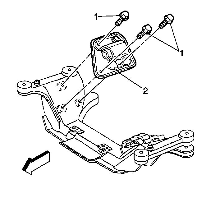
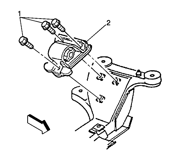
- Remove the right side engine mount (2) to cradle bolts (1).
- Remove the left side engine mount (2) to cradle bolts (1).
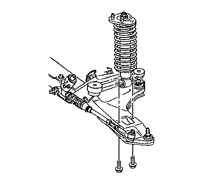
- Remove the right and left side shock absorber lower mounting bolts.
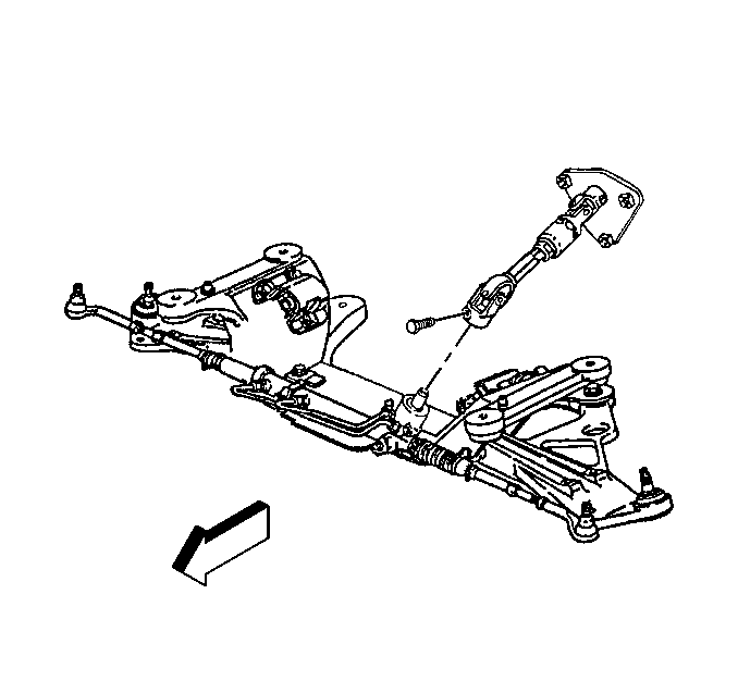
- Remove the intermediate steering shaft bolt from the rack and pinion.
- Support the engine cradle with appropriate equipment.
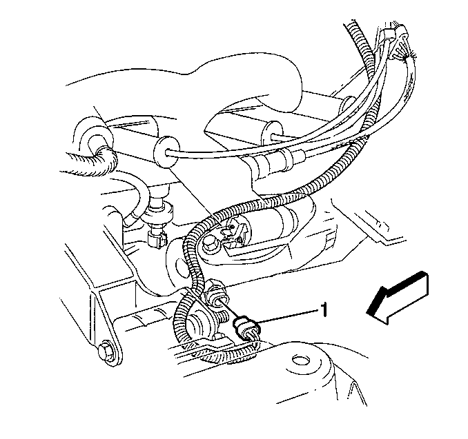
- Disconnect the oil level sensor electrical connector (1).
- Remove the oil level sensor from the oil pan.
- Remove the starter motor. Refer to Starter Motor Replacement .
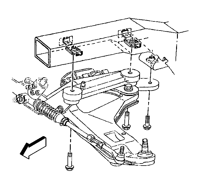
- Remove the front crossmember bolts.
- Remove the oil pan bolts (1).
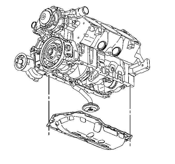
- Remove the oil pan (2).
- Remove the oil pan gasket.
- Clean the oil pan gasket mating surface.
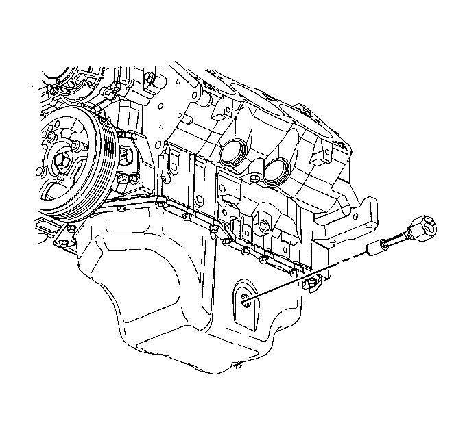
Notice: Remove the oil level sensor, located in the oil pan, before the oil pan is removed. The sensor may be damaged if the oil pan is removed first.
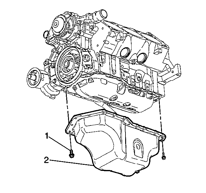
Lower the rear of the oil pan while rotating the pan outward.
Installation Procedure
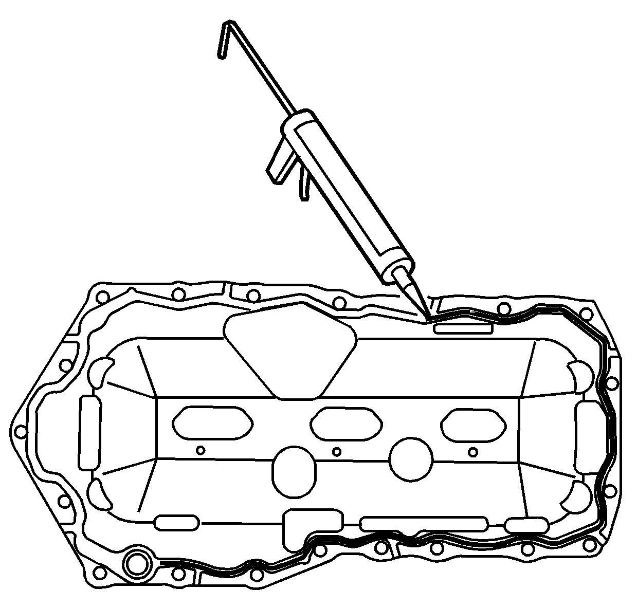
- Apply a continuous bead 6.35 mm (0.25 in) thick of RTV sealer GM P/N 12378521 (Canadian P/N 88901148) to the bottom side of the new gasket. Apply the RTV sealant directly over the gaskets sealing bead.
- Install the oil pan gasket.
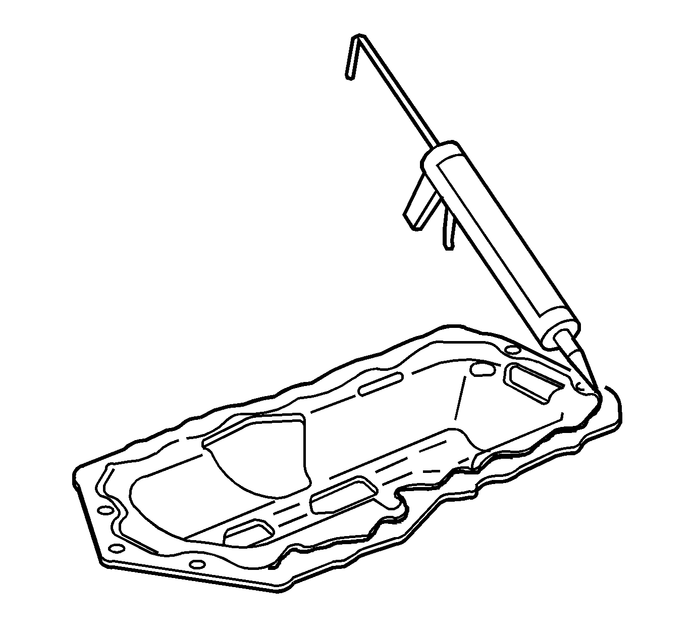
- Apply a continuous bead 6.35 mm (0.25 in) thick of RTV sealer GM P/N 12378521 (Canadian P/N 88901148) to the topside of the new gasket. Apply the RTV sealant directly over the gaskets sealing bead.
- Install the oil pan (2).
- Install the oil pan bolts (1).
- Install the front crossmember bolts.
- Install the starter motor. Refer to Starter Motor Replacement .
- Install the oil level sensor to the oil pan.
- Connect the oil level sensor electrical connector (1).
- Remove the equipment used to support the engine cradle.
- Install the intermediate steering shaft from the rack and pinion.
- Install the right and left side shock absorber lower mounting bolts.
- Install the left side engine mount (2) to cradle bolts (1).
- Install the right side engine mount (2) to cradle bolts (1).
- Lower the vehicle.
- Remove the engine support fixture.
- Change the engine oil and filter. Refer to Engine Oil and Oil Filter Replacement .


Tighten
Tighten the oil pan bolts to 14 N·m (10 lb ft).

Tighten
| • | Tighten the upper four crossmember bolts to 125 N·m (92 lb ft). |
| • | Tighten the lower two crossmember bolts to 145 N·m (107 lb ft). |

Tighten
Tighten the oil level sensor to 20 N·m (15 lb ft).


Tighten
Tighten the intermediate shaft bolt to 47 N·m (35 lb ft).

Tighten
Tighten the shock bolts to 65 N·m (48 lb ft).

Tighten
Tighten the left side engine mount to cradle bolts (1) to 58 N·m (43 lb ft).

Tighten
Tighten the right side engine mount to cradle bolts (1) to 58 N·m (43 lb ft).
