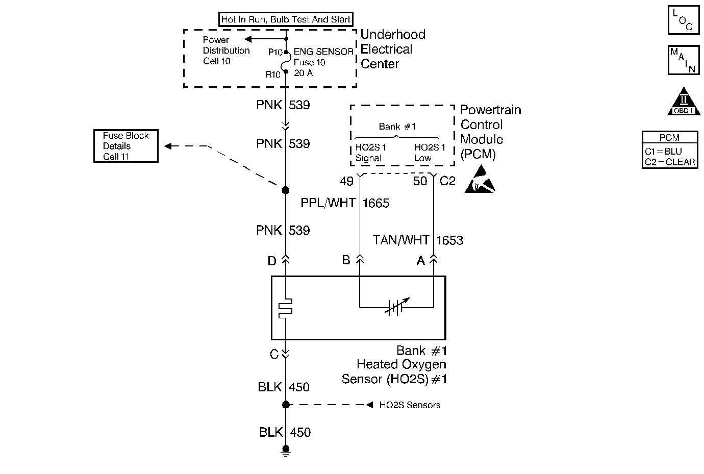
Circuit Description
The PCM continuously monitors the Heated Oxygen Sensor (HO2S) activity. The PCM counts the number of times that a rich to lean and a lean to rich response is indicated. Then, the PCM adds the amount of time it took to complete all transitions for a 100 second test period. With this information, an average time for each transition can be determined. If the average response time is too slow, a DTC P0133 will be set. A lean to rich transition is indicated when the HO2S voltage changes from less than 300 mV to greater than 600 mV. A rich to lean transition is indicated when the HO2S voltage changes from greater than 600 mV to less than 300 mV. An HO2S that responds too slowly is likely to be faulty and should be replaced.
Conditions for Setting the DTC
| • | No active transmission, TP sensor, EVAP system, EGR, misfire, IAT sensor, MAP sensor, fuel trim, fuel injector circuit, EVAP solenoid ODM, ECT sensor, or MAF sensor DTC(s) present |
| • | DTC P0135 (HO2S Heater) not set |
| • | The engine has been running in closed loop for at least 2 minutes. |
| • | Engine speed is between 1000 RPM and 3000 RPM. |
| • | Engine Coolant Temperature greater than 50°C (122°F). |
| • | Mass Air Flow between the following limits: |
| • | Automatic Transmission - Between 15 gm/s and 29 gm/s. |
| • | Manual Transmission - Between 10 gm/s and 30 gm/s. |
| • | Bank 1 H02S 1 lean to rich or rich to lean average transition response time was longer than 90 milliseconds. |
Action Taken When the DTC Sets
| • | The PCM will illuminate the MIL during the second consecutive trip in which the diagnostic test has been run and failed. |
| • | The PCM will store conditions which were present when the DTC set as Freeze Frame and Fail Records data. |
Conditions for Clearing the MIL/DTC
| • | The PCM will turn the MIL OFF during the third consecutive trip in which the diagnostic has been run and passed. |
| • | The history DTC will clear after 40 consecutive warm-up cycles have occurred without a malfunction. |
| • | The DTC can be cleared by using the scan tool Clear Information function or by disconnecting the PCM battery feed. |
Diagnostic Aids
Check for the following conditions:
| • | Poor connection at the PCM - Inspect harness connectors for the following conditions: |
| - | Backed out terminals. |
| - | Improper mating. |
| - | Broken locks. |
| - | Improperly formed or damaged terminals. |
| - | Poor terminal to wire connection. |
| • | Damaged harness -- Inspect the wiring harness for damage. If the harness appears to be OK, observe the Bank 1 H02S 1 display on the scan tool while moving connectors and wiring harnesses related to the sensor. A change in the display will indicate the location of the fault. |
If DTC P0133 cannot be duplicated, Review the Fail Records vehicle mileage since the diagnostic test last failed. This may help determine how often the condition that caused the DTC to be set occurs.
Test Description
Number(s) below refer to the Step number(s) on the Diagnostic Table:
-
This step verifies that the fault is currently present.
-
HO2S transition time, ratio mean volts and switching DTCs set for multiple sensors indicate probable contamination. Before replacing the sensors, isolate and correct the source of the contamination to avoid damaging the replacement sensors.
Step | Action | Value(s) | Yes | No | ||||||||
|---|---|---|---|---|---|---|---|---|---|---|---|---|
1 | Was the Powertrain On-Board Diagnostic (OBD) System Check performed? | -- | ||||||||||
|
Important: If any DTCs are set,(Except P0153, P1133, P1134, P1135, P1136, P1153, P1154, P1155, and/or P1156), refer to those DTCs before proceeding with this diagnostic table.
Does scan tool indicate DTC P0133 failed this ignition? | -- | Refer to Diagnostic Aids | ||||||||||
Did the scan tool also indicate DTC P0153, P1133, P1134, P1135, P1136, P1153, P1154, P1155, and/or P1156 failed this ignition? | -- | |||||||||||
4 |
Was an exhaust leak isolated? | -- | ||||||||||
5 | Visually/physically inspect the following items:
Was a problem found in any of the above areas? | -- | ||||||||||
6 |
Does the scan tool indicate voltage near the specified value? | 450 mV | ||||||||||
7 |
Does scan tool indicate voltage below specified value? | 300 mV | ||||||||||
8 | Replace affected Heated Oxygen Sensors. Refer to Heated Oxygen Sensor Replacement . Important: : Determine and correct the cause of the contamination before replacing sensors. Check for the following conditions:
Is the action complete? | -- | -- | |||||||||
9 | Repair condition as necessary. Is the action complete? | -- | -- | |||||||||
10 | Repair an open Bank 1 HO2S 1 low signal circuit or a grounded Bank 1 HO2S 1 high signal circuit. Refer to Heated Oxygen Sensor (HO2S) Repair in Electrical Diagnosis. Is the action complete? | -- | -- | |||||||||
11 | Repair open Bank 1 HO2S 1 high signal circuit or faulty PCM connections. Refer to Heated Oxygen Sensor (HO2S) Repair in Electrical Diagnosis. Is the action complete? | -- | -- | |||||||||
12 | Replace Bank 1 HO2S 1. Refer to Heated Oxygen Sensor Replacement . Is the action complete? | -- | -- | |||||||||
13 |
Does the scan tool indicate DTC P0133 failed this ignition? | -- | System OK |
