Cylinder Head Replacement Left Side
Special Tools
J 36660-A Torque Angle Meter
Removal Procedure
- Relieve the fuel pressure.
- Disconnect the fuel lines at the fuel rail.
- Drain the coolant. Refer to SECTION 6B.
- Remove the upper intake manifold. Refer to Intake Manifold Replacement .
- Remove the lower intake manifold. Refer to Intake Manifold Replacement .
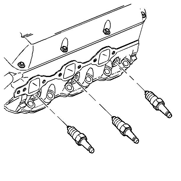
- Remove the spark plugs.
- Remove the left exhaust manifold. Refer to Left Exhaust Manifold Replacement.
- Remove the valve rocker arm cover. Refer to Valve Rocker Arm Cover Replacement .
- Remove the valve rocker arms and pushrods. Refer to Valve Rocker Arm and Pushrod Replacement.
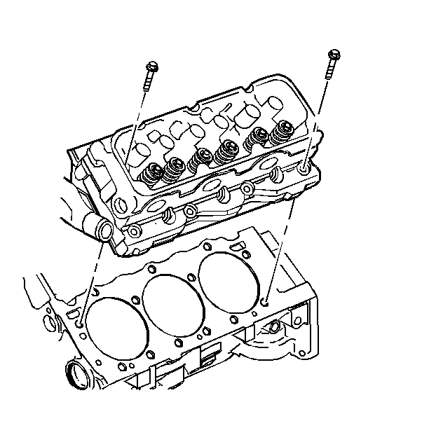
- Remove the cylinder head bolts.
- Remove the cylinder head.
- Clean the engine block threads. Use a 7/16-14 tap.


Installation Procedure
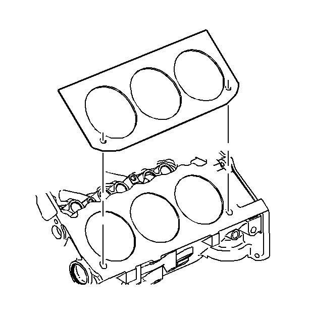
- Install the new cylinder head gasket.
- Install the cylinder head.
- Install the NEW cylinder head bolts.
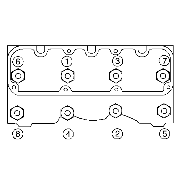
- Tighten the cylinder head bolts to 50 N·m (37 lb ft) in sequence.
- Use the J 36660-A in order to rotate the bolts in sequence 120 degrees.
- Use the J 36660-A in order to rotate the center four bolts an additional 30 degrees in sequence.
- Install the pushrods and the valve rocker arms. Refer to Valve Rocker Arm and Pushrod Replacement.
- Install the valve rocker arm cover. Refer to Valve Rocker Arm Cover Replacement .
- Install the left exhaust manifold. Refer to Left Exhaust Manifold Replacement.
- Install the spark plugs.
- Install the lower intake manifold. Refer to Intake Manifold Replacement .
- Install the upper intake manifold. Refer to Intake Manifold Replacement .
- Refill the engine coolant. Refer to SECTION 6B.
Important: The arrow on the gasket must point to the front of the engine. Failure to install the gasket properly will cause gasket failure and possible engine failure.


Notice: Use the correct fastener in the correct location. Replacement fasteners must be the correct part number for that application. Fasteners requiring replacement or fasteners requiring the use of thread locking compound or sealant are identified in the service procedure. Do not use paints, lubricants, or corrosion inhibitors on fasteners or fastener joint surfaces unless specified. These coatings affect fastener torque and joint clamping force and may damage the fastener. Use the correct tightening sequence and specifications when installing fasteners in order to avoid damage to parts and systems.
Tighten

Tighten
Tighten the spark plugs to 27 N·m (20 lb ft).
Cylinder Head Replacement Right Side
Special Tools
J 36660-A Torque Angle Meter
Removal Procedure
- Relieve the fuel pressure.
- Disconnect the fuel lines at the fuel rail.
- Drain the coolant. Refer to SECTION 6B.
- Remove the upper intake manifold. Refer to Intake Manifold Replacement .
- Remove the lower intake manifold. Refer to Intake Manifold Replacement .
- Remove the spark plugs.
- Remove the right exhaust manifold. Refer to Right Exhaust Manifold Replacement.
- Remove the valve rocker arm cover. Refer to Valve Rocker Arm Cover Replacement .
- Remove the valve rocker arms and the pushrods. Refer to Valve Rocker Arm and Pushrod Replacement.
- Remove the drive belt tensioner. Refer to Drive Belt Tensioner Replacement .
- Remove the rear generator brace.
- Remove the cylinder head bolts.
- Remove the cylinder head.
- Remove the cylinder head gasket.
- Clean the engine block threads using 7/16-14 tap.


Installation Procedure
- Install the new cylinder head gasket.
- Install the cylinder head.
- Install the new cylinder head bolts.
- Tighten the cylinder head bolts to 50 N·m (37 lb ft) in sequence.
- Rotate the bolts to 120 degrees in sequence using the J 36660-A .
- Rotate the center four bolts an additional 30 degrees in sequence using the J 36660-A .
- Install the rear generator brace.
- Install the drive belt tensioner. Refer to Drive Belt Tensioner Replacement .
- Install the pushrods and the valve rocker arms. Refer to Valve Rocker Arm and Pushrod Replacement.
- Install the valve rocker arm cover. Refer to Valve Rocker Arm Cover Replacement .
- Install the right exhaust manifold. Refer to Right Exhaust Manifold Replacement.
- Install the spark plugs.
- Install the lower intake manifold. Refer to Intake Manifold Replacement .
- Install the upper intake manifold. Refer to Intake Manifold Replacement .
- Refill the engine coolant. Refer to SECTION 6B.
Important: The arrow on the gasket must point to the front of the engine. Failure to install the gasket properly will cause gasket failure and possible engine damage.


Notice: Use the correct fastener in the correct location. Replacement fasteners must be the correct part number for that application. Fasteners requiring replacement or fasteners requiring the use of thread locking compound or sealant are identified in the service procedure. Do not use paints, lubricants, or corrosion inhibitors on fasteners or fastener joint surfaces unless specified. These coatings affect fastener torque and joint clamping force and may damage the fastener. Use the correct tightening sequence and specifications when installing fasteners in order to avoid damage to parts and systems.
Tighten


Tighten
Tighten the spark plugs to 27 N·m (20 lb ft).
