PREMATURE CLUTCH WEAR CORRECT USE OF PARTS

Model and Year: 1984-88 FIREBIRD WITH MANUAL TRANSMISSION
Some 1984-88 Firebird models equipped with manual transmissions may exhibit one of the following conditions.
1. REPEATED OR PREMATURE CLUTCH WEAR
This condition in V-6 vehicles may be caused by a loose/bent ball stud or a misinstalled/bent clutch fork. Therefore, prior to changing a clutch assembly in any of these vehicles, check that the ball stud is securely seated in the bell housing. If not, tighten as required. If the ball stud is bent, replace it.
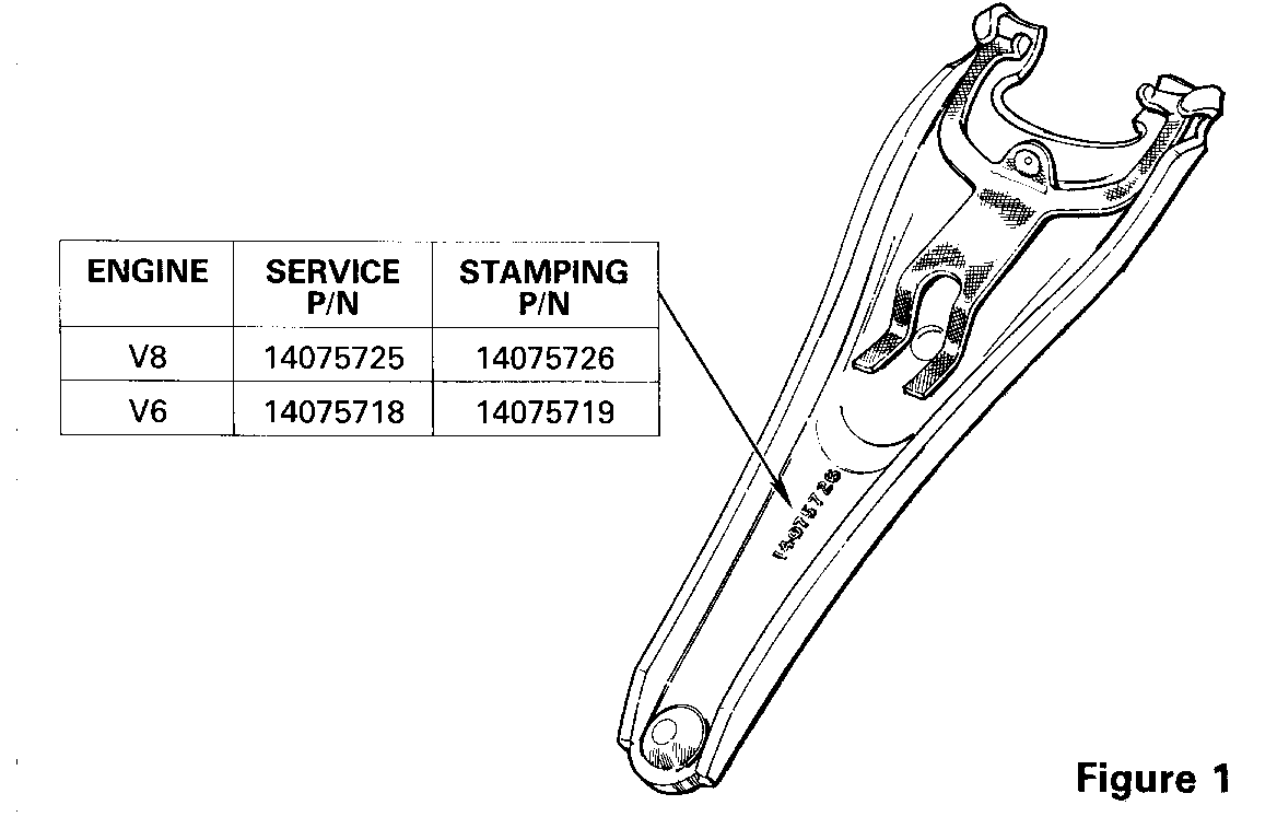
Also, check for proper installation of the fork, P/N 14075718 on the ball stud (i.e., both spring clips under the ball stud shoulder) . If either of the spring clips are bent, replace the clutch fork.
NOTICE: THE PART NUMBER ON THE FORK (SEE FIGURE 1) IS THE STAMPING PART NUMBER AND NOT THE ASSEMBLY PART NUMBER. HOWEVER, THE STAMPING NUMBER DOES CORRESPOND TO AN ASSEMBLY NUMBER, AS SHOWN IN FIGURE 1.
2. LEAKING HYDRAULIC CLUTCH SLAVE CYLINDERS
This condition in V-8 vehicles may be caused by a loose/bent ball stud or a misinstalled/bent clutch fork. Therefore, prior to changing a hydraulic clutch assembly on any of these vehicles, check that the ball stud is securely seated in the bell housing. If not, tighten as required. If the ball stud is bent, replace it.
Also, check for proper installation of the fork, P/N 14075725 on the ball stud (i.e., both spring clip s under the ball stud shoulder). If either of the spring clip s are bent, replace the clutch fork.
NOTICE: THE PART NUMBER ON THE FORK (SEE FIGURE 1) IS THE STAMPING PART NUMBER AND NOT THE ASSEMBLY PART NUMBER. HOWEVER, THE STAMPING NUMBER DOES CORRESPOND TO AN ASSEMBLY NUMBER, AS SHOWN IN FIGURE 1.
3. CLUTCH DRIVEN DISC DAMPER SPRINGS SEPARATED FROM DISC OR HEAVILY WORN CRANKSHAFT PILOT BUSHING.
(Customer comments of noise from clutch/transmission on initial launch or complete loss of clutch.) This condition in V-6 vehicles may be due to misalignment between the clutch housing (transmission) and engine. The misalignment may be caused by one or both of the dowel pins in the rear face of the engine cylinder and case assembly not protruding far enough out of the case.
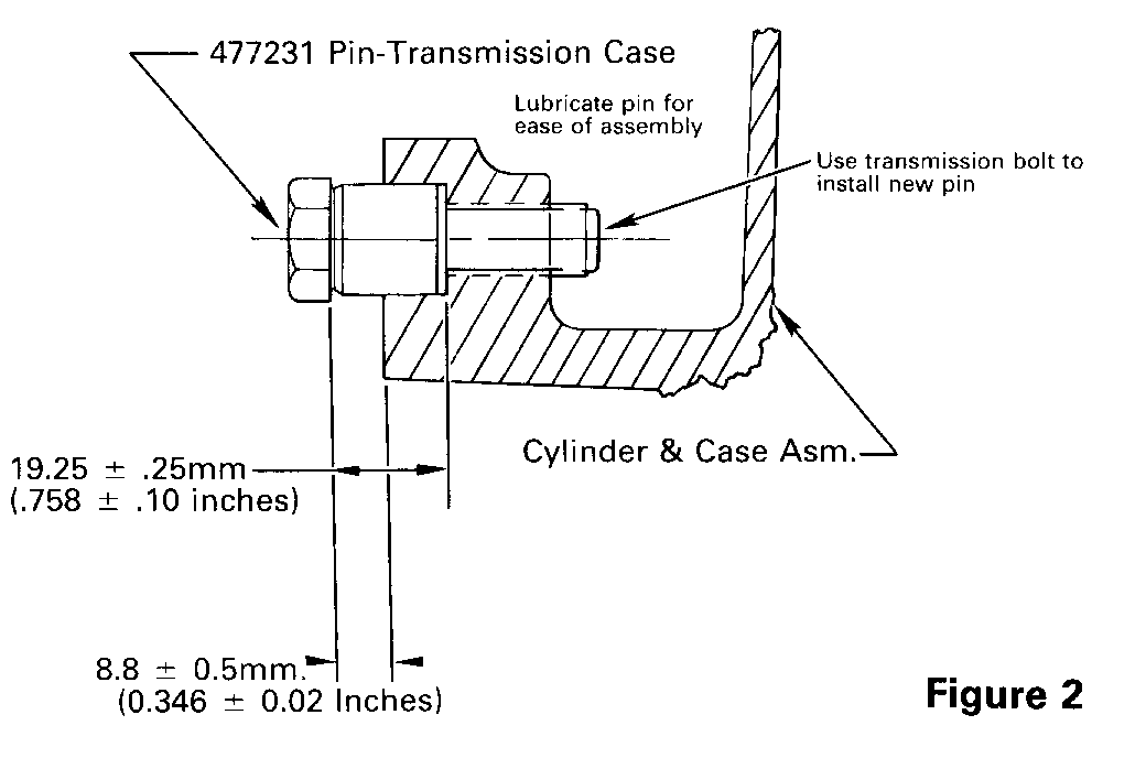
To repair this condition, disassemble the transmission and clutch housing assembly from the vehicle and measure the amount of protrusion for both pins. Each pin should have a minimum of 8.8 mm (.35") protrusion. If less than 8.8 mm the pins should be removed from the case using an "easy out" and large tee handle or other similar method. Then install two new 19 mm (.748") long dowel pins P/N 477231 into the block until the pins protrude 8.8 mm. Use a clutch housing mounting bolt to install the new pins, as shown in Figure 2. Lubricating the pins should ease the installation process.
Parts are currently available from GMSPO.
NOTICE: CARE SHOULD BE TAKEN TO AVOID DAMAGE/DEFORMATION TO THE PRECISION MACHINED LOCATING COUNTERBORES IN THE CYLINDER AND CASE. PARTICULAR CARE SHOULD BE TAKEN TO AVOID CRACKING THE CYLINDER AND CASE.
Use applicable Labor Operation Number and Labor Time.


General Motors bulletins are intended for use by professional technicians, not a "do-it-yourselfer". They are written to inform those technicians of conditions that may occur on some vehicles, or to provide information that could assist in the proper service of a vehicle. Properly trained technicians have the equipment, tools, safety instructions and know-how to do a job properly and safely. If a condition is described, do not assume that the bulletin applies to your vehicle, or that your vehicle will have that condition. See a General Motors dealer servicing your brand of General Motors vehicle for information on whether your vehicle may benefit from the information.
