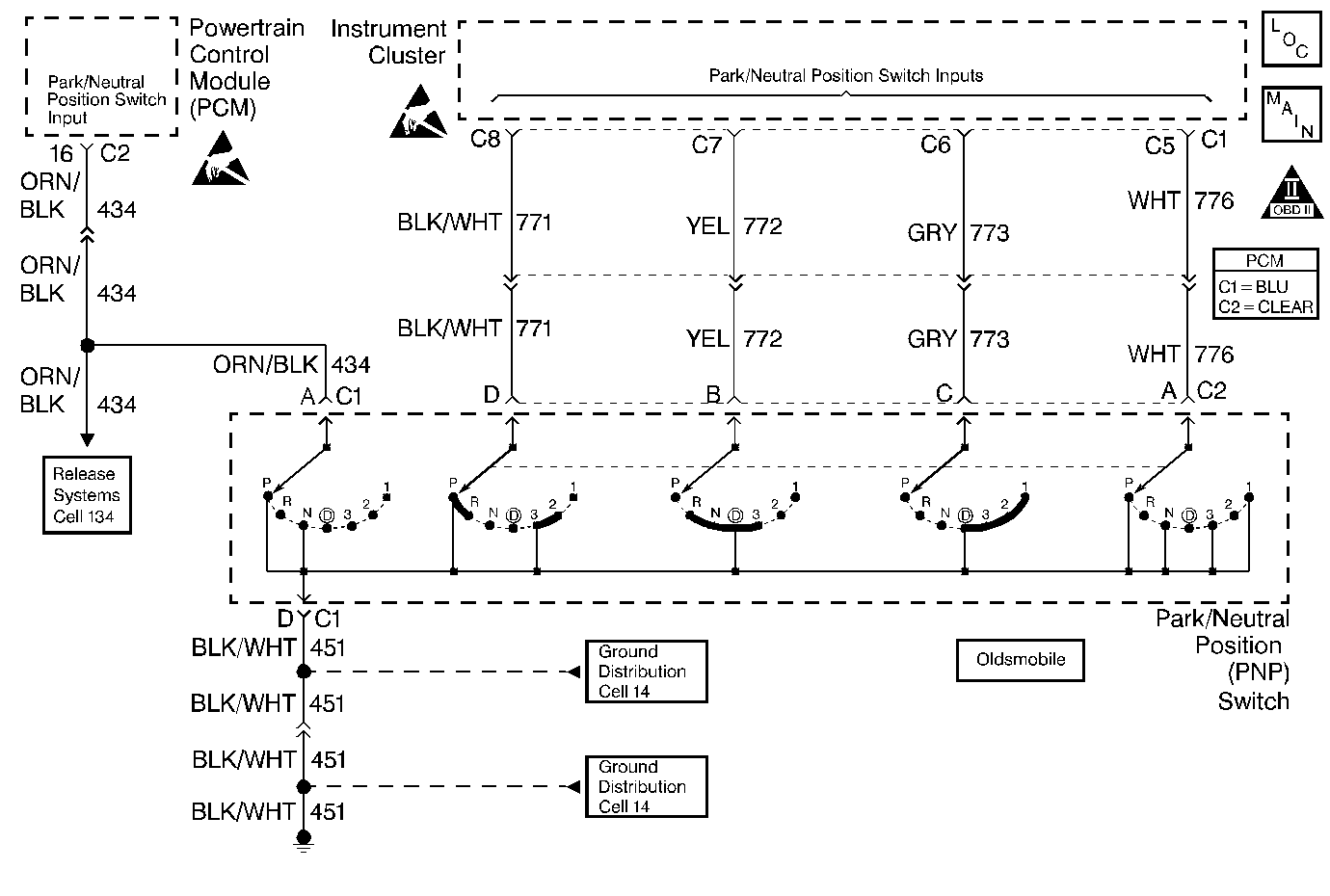
Circuit Description
The Transaxle Range Switch is part of the Transaxle Park/Neutral Position (PNP) switch mounted on the transaxle manual shaft. The four inputs from the transaxle range switch indicate to the PCM which position is selected by the Transaxle selector lever. This information is used for ignition timing, EVAP canister purge, EGR and IAC valve operation. The input voltage level at the PCM is high (B+) when the transaxle range switch is open and low when the switch is closed to ground. The state of each input is available for display on the scan tool. The four parameters represent transaxle range switch Parity, A, B, and C inputs respectively.
A problem with the transaxle range switch adjustment which causes the PCM to detect vehicle startup while a gear position other than Park or Neutral is selected will set DTC P0706.
Gear Selector Position | Scan Tool TR Switch P/A/B/C Display | |||
|---|---|---|---|---|
P | A | B | C | |
Park (P) | Low | Low | High | High |
Reverse (R) | High | Low | Low | High |
Neutral (N) | Low | High | Low | High |
Drive4 (OD) | High | High | Low | Low |
Drive3 (3) | Low | Low | Low | Low |
Drive2 (2) | High | Low | High | Low |
Drive 1 (1) | Low | High | High | Low |
Conditions for Setting the DTC
| • | System voltage (Ignition 1) is greater than 9 volts. |
| • | The transaxle range switch inputs indicate a gear position other than Park or Neutral during startup. |
| • | The above conditions are present for 3 consecutive startups. |
Action Taken When the DTC Sets
| • | The PCM will not illuminate the Malfunction Indicator Lamp (MIL). |
| • | The PCM will store conditions which were present when the DTC set as Fail Records data only. This information will not be stored as Freeze Frame data. |
Conditions for Clearing the MIL/DTC
| • | A history DTC will clear after 40 consecutive warm-up cycles have occurred without a malfunction. |
| • | DTC can be cleared by using the scan tool Clear Info function or by disconnecting the PCM battery feed. |
Diagnostic Aids
DTC P0706 set indicates a misadjusted park neutral position / transaxle range switch.
DTC can set if the PCM loses UART serial data communication or a incorrect PRNDL is detected by the instrument panel
Important:: The vehicle should not be driven with transaxle range switch disconnected, as idle quality will be affected.
Reviewing the Fail Records vehicle mileage since the diagnostic test last failed may help determine how often the condition that caused the DTC to be set occurs. This may assist in diagnosing the condition.
Test Description
Numbers below refer to the step numbers on the Diagnostic Table.
Step | Action | Values | Yes | No |
|---|---|---|---|---|
1 | Was the Powertrain On-Board Diagnostic (OBD) System Check performed? | -- | ||
2 |
Important:: If DTC P0706 is encountered on Oldsmobile, refer to Instrument Cluster System Check in Instrument Panel, Gauges and Console. Is DTC P0705 also set? | -- | ||
3 |
Does Trans Range display indicate P-N? | -- | ||
4 |
Does Trans Range display indicate P-N? | -- | Go to Diagnostic Aids | |
5 | Observe the scan tool TR Switch P / A / B / C display. Does scan tool TR Switch P / A / B / C display the specified values? | P=Low A=Low B=Low C=Low | ||
6 |
Does scan tool TR Switch P / A / B / C display the specified values? | P=Low A=Low B=Low C=Low | ||
7 |
Was a problem found? | -- | ||
8 |
Does the scan tool display P-N with Park and Neutral selected? | -- | ||
9 |
Was a problem found? | -- | ||
10 | Replace the Transaxle Range switch (PNP). Refer to Park/Neutral Position Switch Replacement . Is action complete? | -- | -- | |
|
Important:: The replacement PCM must be programmed. Replace the PCM. Refer to Powertrain Control Module Replacement/Programming . Is action complete? | -- | -- | ||
12 |
Does the scan tool display match the Transaxle Range Switch Valid Combinations table in each gear position? | -- | System OK |
