ASI Resolution - Steering Column Upper Tilt Position Feels Loose (Install New Tilt Stop Bumper)

| Subject: | Steering Column Upper Tilt Position Feels Loose (Install New Tilt Stop Bumper) |
| Models: | 2004-2005 Buick Rendezvous |
| 2004-2005 Pontiac Aztek |
| Built Prior to October 1, 2004 |
This bulletin is being revised to add the Correction Information that is now available for Advanced Service Information Bulletin Number 04-02-35-010. Please discard Advanced Service Information Bulletin Number 04-02-35-010 (Section 2 - Steering).
Condition
Some customers may comment that the steering column upper tilt position feels loose.
Cause
The cause of this condition may be due to a change that was made with the start of 2004 production, where the upper most tilt position was eliminated. However, the steering wheel will still travel upward until it contacts an internal bumper stop. This travel results in a loose feel or that the steering wheel will not lock in the top tilt position.
Correction
Important : The new tilt stop bumper can be obtained from the Warranty Parts Center.
DO NOT REPLACE THE STEERING COLUMN. A new service steering column tilt stop bumper has been released to correct this condition. The increased length of this new bumper will reduce the travel and eliminate the feel that the steering wheel doesn't lock in the top tilt position. Replace the tilt stop bumper using the procedure listed below.
- Disconnect the battery negative cable. Refer to Battery Negative Cable Disconnect/Connect Procedure in Engine Electrical.
- Disable the SIR system. Refer to the SIR Disabling and Enabling Zone 3 procedure in the Service Information (SI Document ID #1402526).
- Remove the knee bolster trim panel.
- Remove the inflatable restraint steering wheel module using J 44298.
- Remove the steering wheel nut and steering wheel using J 1859-A and J 42578.
- Remove the tilt lever close out plate.
- Remove the screws and the lower steering column trim cover.
- Remove the retaining screw from the upper steering column trim cover.
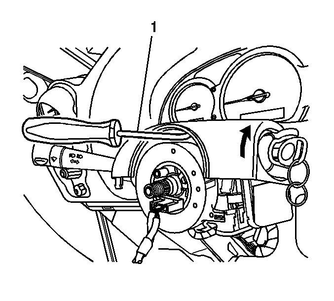
- Lift the upper trim cover in order to gain access to the lock cylinder access hole (1).
- Insert the Snap-On A173A bent-tip awl (1), or equivalent, with a 2.5 mm (3/32 in) tip and 20 mm (3/4 in) in length, into the access hole of the ignition lock cylinder.
- Turn the ignition lock cylinder to START.
- Use the bent tip in order to push down on the ignition lock cylinder retainer.
- Release the ignition lock cylinder to the RUN position.
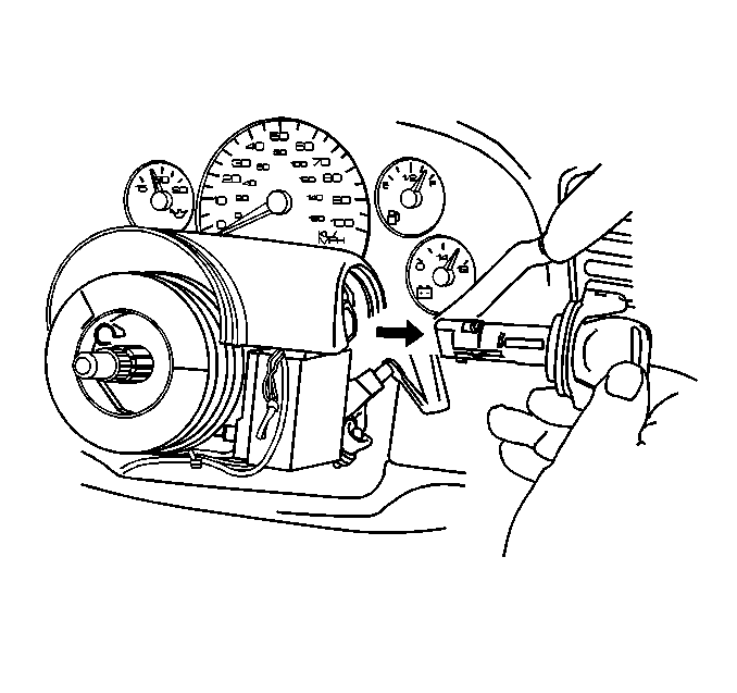
- Remove the ignition lock cylinder from the lock cylinder case.
- Remove the upper steering column cover.
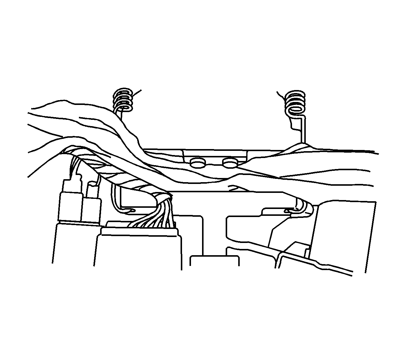
- Place a small cloth between the steering column upper and lower tilt heads as shown. This will prevent the stop bumpers from falling into the steering column when they are removed.
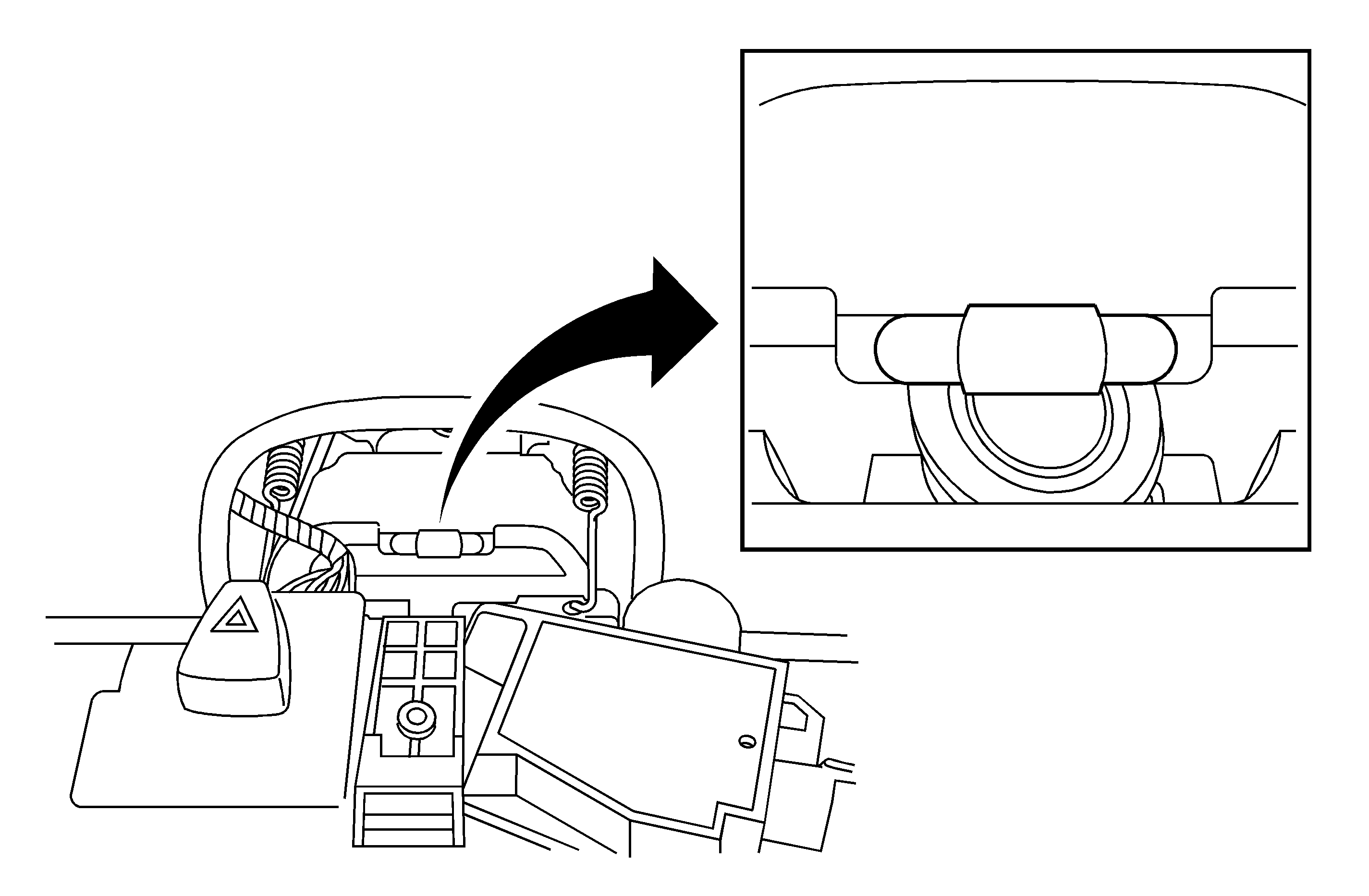
- Remove the two stop bumpers from the steering column lower tilt head.
- Install the new stop bumper into the steering column lower tilt head.
- Install the upper steering column cover.
- Install the ignition lock cylinder into the lock cylinder case.
- Install the retaining screw to the upper steering column trim cover.
- Install the lower steering column trim cover and screws.
- Install the tilt lever close out plate.
- Install the steering wheel and nut.
- Install the inflatable restraint steering wheel module.
- Install the knee bolster trim panel.
- Enable the SIR system. Refer to the SIR Disabling and Enabling Zone 3 procedure in the Service Information (SI Document ID #1402526).
- Connect the battery negative cable. Refer to Battery Negative Cable Disconnect/Connect Procedure in Engine Electrical.


Tighten
Tighten the nut to 41 N·m(30 lb ft).
Parts Information
To obtain the new tilt stop bumper, fax the form included in this bulletin to the GM Warranty Parts Center.
Warranty Information
For vehicles repaired under warranty, use:
Labor Operation | Description | Labor Time |
|---|---|---|
E9421* | Bumper, Steering Column Tilt Stop -- Replace | 0.7 hr |
*This is a unique labor operation number for use only with this bulletin. This number will not be published in the Labor Time Guide.
Dealer Actions
| • | Please contact all customers that were told they would be called when a repair became available. |
| • | Distribute this information to all dealership technicians and service advisors. |
Fax the completed request form to: GM Warranty Parts Center Attention: Jeannette Dunn Fax #: 248-371-0192 | |
|---|---|
VIN: _________________________________________________
| |
R.O. #: _________________________
| |
Dealer Information:
| |
Dealer/BAC Code: ____________________
|
Phone #: _____________________
|
Dealer Name: _____________________________________________________
Address: ________________________________________________________
________________________________________________________________
| |
Technician: _____________________________________________________ | |
Important: If you do not receive the part within 2 business days after faxing your part request to the Warranty Parts Center, please call Customer Assistance at 248-371-9901/9902.
