REAR BRAKE DRAG(MODELS W/ABS) DIAGNOSIS AND REPAIR

VEHICLES AFFECTED: 1986-87 6000 STE WITH ABS
CAUTION:
BE SURE ENGINE IS OFF BEFORE PERFORMING THE FOLLOWING PROCEDURES.
Some vehicles may experience brake drag. Brake drag can be evaluated by elevating the rear wheels so the wheels can rotate freely. With the engine off, place the ignition switch in the RUN position and release the park brake. After the brake accumulator has reached operating pressure and the pump motor has stopped running, check for brake drag. If the wheels fail to rotate freely, the following should be checked and repaired. (Leave the ignition switch in the RUN position while making the following tests.)
1. Make sure the park brake is fully released and caliper park brake levers are against the stops.
2. Check the brake light and cruise control switch adjustments by pulling rearward on the service brake pedal.
3. Lightly pull rearward on the service brake pedal, and have someone check to see if the rear wheels turn freely. Release the pedal and recheck for brake drag.
4. If the wheels are free from drag after the brake pedal is pulled rearward and released, make a normal service brake apply, release slowly and recheck for drag.
5. If drag returns after the normal brake apply in Item 4, visually inspect for the following and repair as necessary:
a. Interference of the service brake pedal arm to the hush panel.
b. Interference between the brake light/cruise switch bracket and the pedal arm.
c. Interference between the brake light/cruise switch body and the radius at the end of the machined surface on the rear edge of the brake pedal arm (See Figure 3).
d. Binding between the pushrod eyebolt and attaching hardware at the service brake pedal arm.
6. If Item 5 did not indicate a problem or if other attempts fail to repair the drag condition, proceed as follows:
a. Slowly apply the service brake pedal by hand (be sure the ignition is still in the RUN position).
b. There should be approximately 7mm (1/4 inch) of travel before rear brakes begin to apply and a slight increased pedal resistance is encountered. (The pedal is always under spring load and should never feel loose).
c. If there is little or no forward travel of the service pedal before resistance is felt, pull rearward on the pedal and immediately release it. The pedal should remain within approximately 1.5mm (1/16 inch) of the maximum rearward travel.
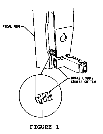
d. If the pedal drops forward more than 1.5mm or 1/16 inch when pulled rearward and released, check for looseness of the push-rod eyebolt end. (See Figure 1). Tighten as necessary using procedure outlined in item e.11.
e. If the pedal still does not have approximately 7min (1/4 inch) of travel before a slight resistance is encountered and the rear brakes begin to apply, improper pushrod to hydraulic unit engagement is indicated. Proper pushrod to hydraulic unit engagement can be accomplished as follows:
1. Turn ignition off and discharge system pressure. (Apply the brake pedal 25 times until a hard pedal is achieved).
2. Disconnect the pedal pushrod from the pedal arm.
3. Unscrew and remove the eyebolt end of the pushrod using a 14m wrench to hold the pushrod (See Figure 1 and 2 for wrench location).
4. Remove the four brake lines from the hydraulic unit.
5. Remove the two vertical bolts attaching the hydraulic unit to the pushrod bracket assembly.
6. Remove the complete hydraulic unit with pushrod attached and place on a suitable work surface.
7. Remove the pushrod and rubber retainer from the hydraulic unit. Discard the pushrod and retainer (do not discard the eyebolt end).
8. Visually inspect the pushrod cavity and remove any particles left from the original rubber retainer (see Fig. 2). Denatured alcohol may be used to clean the cavity.
9. Using a light quantity of silicone grease, manually insert the pushrod-retainer assembly into the hydraulic unit (see Figure 2). The pushrod should "snap" in place when fully seated and must withstand removal loads of 89 N (20 lbs.).
10. Reinstall the main hydraulic unit to the pushrod bracket assembly and retorque attaching bolts to 40-45 N.m (30-33 ft. lbs.).
11. Install the eyebolt on the new pushrod using a torque of 12-15 N.m (9-11 ft. lbs.). The pushrod should be held from rotating with a 14 m m end wrench. (For wrench location see Figures I and 2).
12. Reinstall the pushrod to the service brake pedal arm torquing the attaching nut to 35-40 N.m (26-29 ft. lbs.).
13. Reattach the brake pipes and bleed the system.
14. Readjust brake light and cruise switches.
15. With rear wheels free to rotate, place the ignition switch in the RUN position. After the brake accumulator has reached operating pressure and the pump motor has stopped, depress and release the service brake pedal several times. The pedal should return fully each time, and the rear wheels should rotate freely.
Use applicable Labour Operation and Time.


General Motors bulletins are intended for use by professional technicians, not a "do-it-yourselfer". They are written to inform those technicians of conditions that may occur on some vehicles, or to provide information that could assist in the proper service of a vehicle. Properly trained technicians have the equipment, tools, safety instructions and know-how to do a job properly and safely. If a condition is described, do not assume that the bulletin applies to your vehicle, or that your vehicle will have that condition. See a General Motors dealer servicing your brand of General Motors vehicle for information on whether your vehicle may benefit from the information.
