STEERING WHEEL RADIO CONTROLS REVISED DIAGNOSTICS

1986 6000 STE
When diagnosing the 1986 6000 STE Steering Wheel Radio Controls, use ONLY the information provided in the attached sheets. These sheets are a copy of the Service Manual Section 9H, 'Steering Wheel Radio Controls'. It is imperative that only the Section 9H material be used, as the diagnostics published in Section 8A-150-2 through 8A-150-5 are erroneous and incomplete. Use of the Section 8A diagnostics may result in misdiagnosis and/or damage to the system. The wiring diagrams shown on pages 8A-150-0/ 8A-150-1 may be used as published.
SECTION 9H STEERING WHEEL RADIO CONTROLS -----------------------------
NOTICE: The steering wheel Remote Control Head is susceptible to electrical damage from electrostatic discharge, or ESD. When performing any type of service on the Remote Control Head/Radio system you MUST discharge yourself of static electricity by touching a good vehicle ground, such as the door post or shift lever. Failure to do so may result in damage to the Control
Head/Radio, requiring repair at an AC-Delco Repair Station. If for any reason you leave the vehicle while servicing the system, after re-entering to continue work you must ground yourself and drain any static electrical charge. If performing Control Head/Radio checks on a new vehicle, remove the plastic seat covers, as they increase the possibility of creating a static charge.
CONTENTS
General Description 9H-1 ControlOperation 9H-1 Circuit Operation 9H-1 Diagnosis 9H-1 System Check 9H-1 Check Chart 9H-1 Speaker Test 9H-3
Antenna Test 9H-3 Control Head Power Supply Test 9H-3 Connector Chart 9H-3 Optical/Slipring Test 1 9H-4 Optical/Slipring Test 2 9H-4 Remote Control System Test 9H-5
GENERAL DESCRIPTION
CONTROL OPERATION
For operation of steering wheel radio controls, see Section 9A.
CIRCUIT OPERATION
The remote radio system consists of a multifunction Remote Control Head and data transmitter located in the steering wheel, a slipring and rotating optical data link in the steering column, and an ARC (Advanced Radio Concept) radio equipped with a serial data port for remote control.
Power for the Control Head electronics is taken from the radio fuse, and is supplied to the Control Head through a slipring. The ground and button illumination power are also supplied to the Control Head through the sliprings (see Section 8A for wiring diagrams).
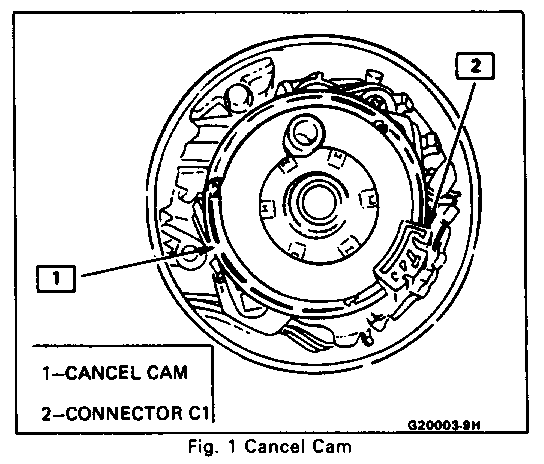
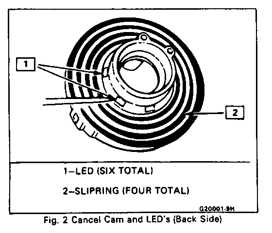
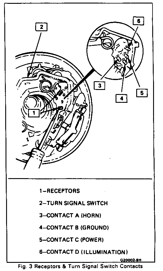
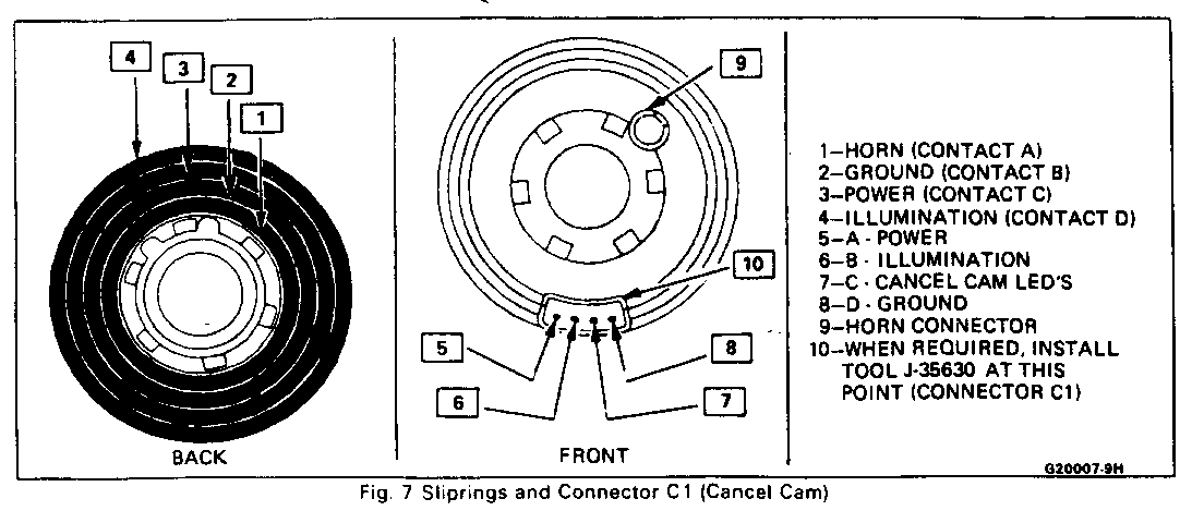
The Remote Control Head controls the radio by generating a unique data word for each operating function when the button controlling that function is pressed. The data words are converted from an electronic signal to an optical signal by the light emitters (LED's) in the steering column cancel cam (see Figures 1 and 2). The light signal then crosses the air gap to the light detector (receptor: Figure 3) located in the turn signal switch, where it is reconverted to an electronic signal. This signal is then routed through wiring to the radio. The radio responds to this control signal and performs the desired action.
DIAGNOSIS
Refer to Section 8A-150 for wiring diagrams of the radio, remote control head and associated components.
Numbers in parentheses( ) next to wire colors refer to wire numbers on the diagrams in Section 8A.
Important
It is very important to follow all procedures carefully and completely to assure proper diagnosis and service of the Remote Control Head/Radio system. Failure to do so may result in misdiagnosis or damage to the system. Of equal importance is discharging yourself of static electricity before working on the system. See 'NOTICE' at the beginning of this section.
SYSTEM CHECK
1. Check Chart ----------- Use the following chart to check the operation of both the instrument panel radio and the Remote Control Head on the steering wheel. Perform the operation given Column 1, and look for the result given in Column 2. If you do not get the expected result, see Column 3 for the appropriate action to take. Letters/numbers in parentheses after a fuse reference indicate the color/amperage rating of the fuse. 'CC' indicates the fuse is located in the Convenience Center. Throughout the chart, and Section 9H in general, the instrument panel unit will be referred to as 'radio' and the steering wheel controls as 'control head'.
SOUND SYSTEM CHECK CHART
OPERATION(l) EXPECTED RESULT(2) DIAG. ACTION(3)
1. With IGN Switch off, a. Time display appears a. Check ARC Radio fuse press RCL control on momentarily, (YEL/20;CC). radio b. Check ORN (340) wire.
2. Turn IGN switch to a. Time display appears. a. Check Radio fuse RUN OR ACCY. (RED/ 10). b. Check YEL (43) wire to splice S239 and Radio fuse (RED/ 10).
3. With IGN switch in a. Power Antenna a. See 8A-151; Power RUN or ACCY, turn extends. Antenna. radio on and tune in b. Program is heard b. See 'Speaker Test'; a local station. from all speakers. System Check #2. Center balance and c. See 'Antenna Test'; fade controls. System Check #3.
4. With IGN switch a. Radio responds to a. If all controls do in RUN or ACCY, all controls. not work properly, operate all send radio to an AC-Delco controls at radio. Repair Station.
5. With IGN switch a. Radio digital a. Check BRN (9) wire in RUN or ACCY and display dims. for voltage to ground. radio on, turn on If wire is good, send headlights or park- radio to an AC-Delco ing lights. Set Repair Station. I/P lights to b. Radio panel lamp b. Check tail lamp fuse maximum brightness. lights. (YEL/20). Check I/P lamps fuse (TAN/5) if control head illumination is also out. Check GRY (8) wire. Check LT.BLU/BLK (151) ground wire. c. Control head c. Check I/P lamps fuse illumination lights (TAN/5) if radio panel evenly. light is also out. Check control head illumination bulbs. If bulbs are good but not lighting, perform 'Control Head Power Supply Test'. 6. With engine running a. Control head a. Perform 'Control Head and headlights or illumination remains Power Supply Test'. parking lights on, lit, with no flickering turn steering wheel as wheel is turned. slowly from lock to lock.
7. With engine a. Radio responds to a. If the tuning controls running, headlights or tuning controls operate at some steering parking lights on and smoothly with no wheel positions, but radio on, operate the interruptions as not all, perform 'Control TUNE:UP and TUNE:DOWN the steering wheel is Head Power Supply Test' controls while turning turned. and 'Optical/Slipring Test the steering wheel from 1' at several steering lock to lock. wheel positions.
8. With IGN switch in a. Radio responds to a. If button is RUN or ACCY and radio all controls. All inoperative and does on, operate all control buttons have a similar not have a similar head controls. "feel". "feel" to all the others, repair/replace control head.
b. If all buttons "feel" good and some buttons do operate, perform 'Remote Control System Test'. c. If no buttons operate and illumination is also out, perform 'Control Head Power Supply Test'. d. If no buttons operate and illumination is on, perform 'Control Head Power Supply Test', 'Remote Control System Test, then 'Optical/ slipring Test 1' until the problem is found.
2. SpeakerTest
If one or more speakers does not operate, test by substituting a known-good speaker designed for an ARC radio. If the substitute speaker works, replace the speaker. If the substitute speaker does not work, check the wiring to that speaker by connecting the substitute speaker directly to the radio.
3. Antenna Test
Check connectors at radio and antenna ends of coaxial antenna cable. Connect a known-good test antenna to the radio. The test antenna must be designed for use with ARC radios, as ARC radios use a different size of antenna connection than conventional radios. Replace the antenna and/or coaxial cable if the test antenna works.
CONTROL HEAO POWER SUPPLY TEST
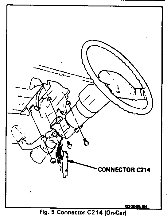
To expose the connector used in this test, remove the steering column filler panel (see Figure 103; Section 8C). See Figure 5 for the on-car connector location.
Connector Chart
Figures 5 and 6
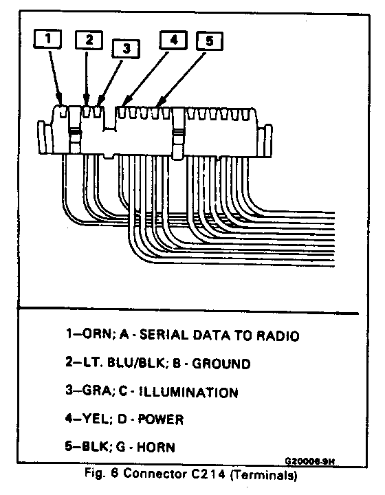
This chart is used in thc same way as the 'Sound System Check Chart'. With connector C214 still connected, backprobe the terminals on C214 given in Column 1, and check for the proper result given in Column 2. If you do not get the expected result given in Column 2, see Column 3 for the appropriate action to take.
All tests in this chart are to be performed with conntctor C214' still connected and with the IGN switch in the RUN or ACCY position.
CONNECTOR CHART
TERMINALS(1)) EXPECTED VOLTAGE(2) DIAG. ACTION (3)
1. D (YEL) to ground. 1. Battery voltage. 1. Check YEL (43) wire. 2. D (YEL) to B (LT. 2. Battery voltage. 2. Check LT. BLU/BLK BLU/BLK). (151) wire. 3. C (GRA) to B (LT. 3. Battery voltage when 3. Check GRA (8) wire. BLU/BLK). headlights are on and I/P lamps are not dimmed.
If all measurements at connector C214 are good, perform 'Optical/Slipring Test 1'.
OPTICAL/SLIPRING TEST 1 ----------------------- Tools Required:
J-35630; Horn Tower Test Adapter
Important
See 'NOTICE' on page 9H-1 of this section.
The control head is held to the steering wheel assembly with velcro, and must be removed to perform this test.
All references to terminals (A,B,C,D) are for the terminals on tool J-35630, not connector Cl on the cancel cam.
Remove or Disconnect
1. Control head by grasping firmly and pulung off steering wheel. Take care not to damage the wiring by pulling the control head off too harshly. 2. BLK (151) ground wire from steering wheel. 3. BLK (28) horn wire from steering wheel.
4. Connector C1 from cancel cam by lifting external tab with small screwdriver to unlock connector.
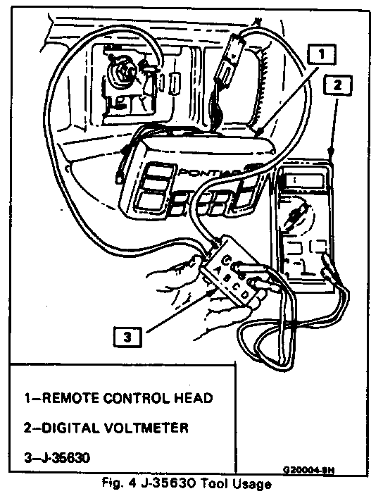
Install tool J-35630 between the control head and connector C1 on cancel cam in steering column (see Figure 4).
All tests in this chart are to be performed while turning the steering wheel slowly, with the engine running. Use a conventional (analog; swing-needle) voltmeter to make the checks at the teminals, as a digital voltmeter may not respond quickly enough to locate a small open in the circuit.
SLIPRING CHART
TOOL TERMINAL VOLTAGE
1. A to ground. 1. Battery voltage at all wheel positions. 2. A to D. 2. Battery voltage at all wheel positions. 3. B to D. 3. Battery voltage at all wheel positions when headlights or parking lights are on and I/P lighting is at maximum brightness.
If battery voltage is not present, or if it varies or 'flutters' during any of the above checks, remove the cancel cam (see Figures 1 and 2). To access the cancel cam, remove the upper steering shaft nut, steering wheel, cover, retaining ring and shaft lock plate. See Section 3B4 for removal procedures. Inspect the sliprings (Figure 2) on the cancel cam, and the contacts and springs in the turn signal switch (see Figure 3). Replace these parts as necessary. Incorrect or missing lubricant on the cancel cam will cause premature failure. The correct lubricant is Part No. 26002312. Take care to keep the lubilcant (or any foreign matter) away from the LED's and receptors, as it will hinder or prevent proper operation.
OPTICAL/SLIPRING TEST 2
All checks in this test are to be made with connector C214 still connected, with the IGN switch in the RUN or ACCY position, and with the cancel cam, turn signal switch and shaft lock in place. Use a conventional analog voltmeter for voltage checks.
A. Backprobe connector C214 terminal A [ORN (917) wire] to ground (do not press any control head buttons during this test). If voltage is between 4.5 and 5.5 volts, go to Step B. If not, inspect/replace turn signal switch (see Figure 3). Turn signal switch replacement procedures are in Section 3B4.
B. Backprobe connector C214 terminal A [ORN (917) wire) to ground while pressing all three of either 'Preset, Mute and Recall' buttons or 'Seek, Scan, and AM/FM' buttons at once. Turn the steering wheel slowly while measuring. If voltage is between 2.0 and 3.0 volts at all wheel positions, check ORN (917) wiring to radio. If wiring is OK, send radio to an AC-Delco Repair Station. If voltage is not always between 2.0 and 3.0 volts, go to Step C.
C. Using tool J-35630 connected between connector C1 on the cancel cam and the control head (see Figure 4), measure voltage from tool terminal C to ground while pressing all three of either 'Preset, Mute, and Recall' buttons or 'Seek, Scan, and AM/FM' buttons at once. Tutn the steering wheel slowly while measuring. If the voltage is between 3.0 and 4.5 volts at all wheel positions, go to Step D. If not, repair/replace control head.
To perform the checks in Step D, the cancel cam must be removed. To access the cancel cam, remove the upper steering shaft nut, steering wheel, cover, retaining ring and shaft lock plate. See Section 3B4 for removal procedures. The turn signal switch receptors must be shielded from outside light during this test. Use a large dark cloth, jacket, or similar item to shield the switch and receptors from lights.
1. Remove the cancel cam, and direct a flashlight beam at the turn signal switch receptors (see Figure 3). Measure the voltage to ground at Pin A of connector C214 (see Figure 6).
- if the voltage is 5 volts when the switch and receptors are in darkness and drops to 0 volts when in the flashlight beam, the slipring is at fault. Replace the cancel cam/slipring.
- if the voltage remains at 5 volts when in the flashlight beam, replace the turn signal switch.
REMOTE CONTROL SYSTEM TEST
The checks in this test are to be performed with the IGN switch in the RUN or ACCY position, with connector C214 still connected. Use a digital voltmeter for all voltage checks.
Backprobe connector C214 Pin A [ORN (917) wire] to ground while pressing all three of either 'Preset, Mute, and Recall' buttons or 'Seek, Scan, and AM/FM' buttons at once. If the voltage drops from approximately 5.0 to 2.5 volts when either group of three buttons is pressed, the control head is good. Check ORN (917) wire and radio. If the voltage does not drop from approximately 5.0 to 2.5 volts when either group of three buttons is pressed, repair/replace control head.
General Motors bulletins are intended for use by professional technicians, not a "do-it-yourselfer". They are written to inform those technicians of conditions that may occur on some vehicles, or to provide information that could assist in the proper service of a vehicle. Properly trained technicians have the equipment, tools, safety instructions and know-how to do a job properly and safely. If a condition is described, do not assume that the bulletin applies to your vehicle, or that your vehicle will have that condition. See a General Motors dealer servicing your brand of General Motors vehicle for information on whether your vehicle may benefit from the information.
