Removal Procedure
- Disconnect the negative battery cable (power sliding door only).
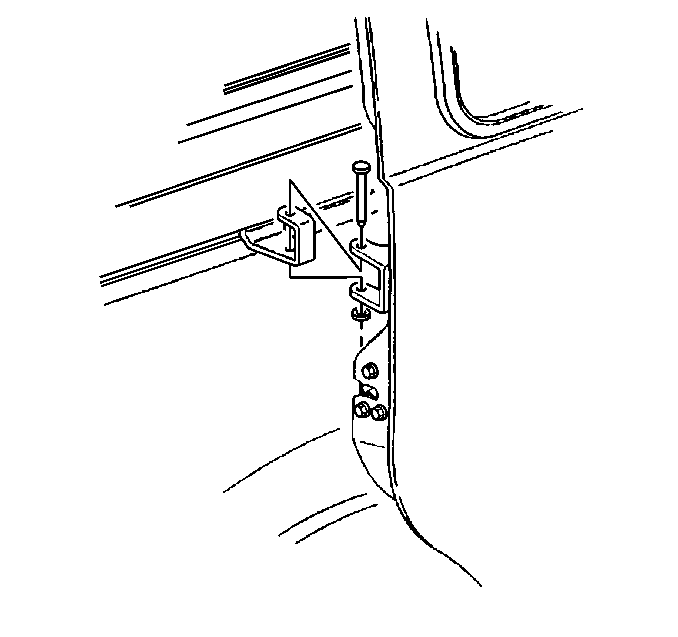
- Open the sliding door in order to gain access to the center roller bracket pin.
- Support the rear sliding door.
- Remove the pin from the center roller bracket.
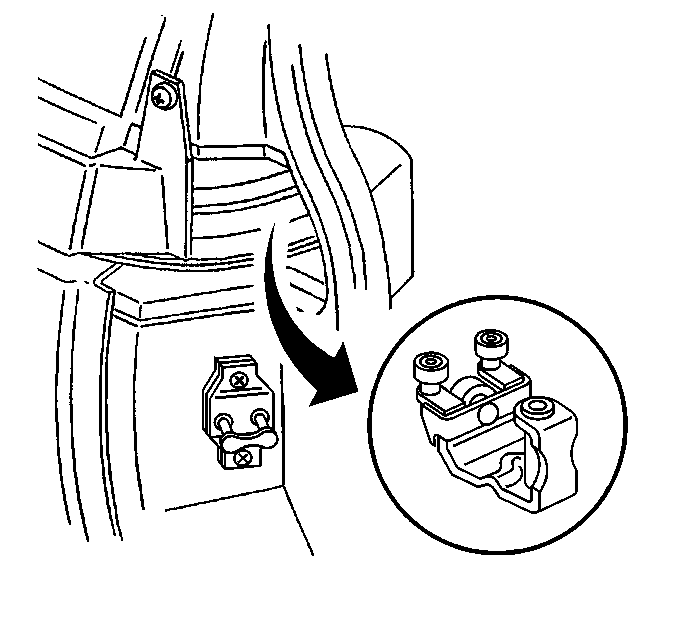
- Position the center roller bracket to the front radius of the sliding door center track.
- Remove the right rear quarter trim.
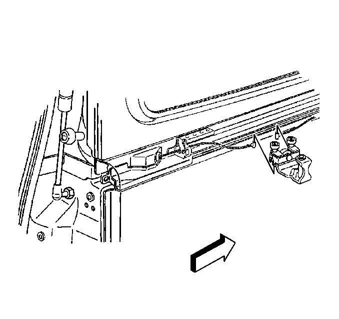
- Release cable tension by positioning the center roller bracket to the front radius of the sliding door center track. Ensure that the cable tension adjuster is accessible in the adjuster window.
- For extended wheel base models only, release the cable tension by pulling out on the adjuster nut using pliers while pulling the rear cable until slack appears.
- For regular wheel base models only, release the cable tension by pushing the adjuster nut inwards while pulling the rear cable until slack appears.
- Lift the center roller bracket upwards and remove the bracket from the center track.
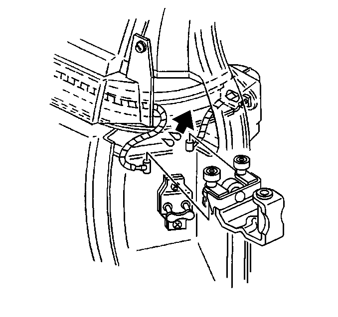
- Detach the cable ends (power sliding door only).
Caution: Unless directed otherwise, the ignition and start switch must be in the OFF or LOCK position, and all electrical loads must be OFF before servicing any electrical component. Disconnect the negative battery cable to prevent an electrical spark should a tool or equipment come in contact with an exposed electrical terminal. Failure to follow these precautions may result in personal injury and/or damage to the vehicle or its components.
Refer to Battery Negative Cable Disconnection and Connection in Engine Electrical.

Refer to Rear Quarter Lower Trim Panel Replacement in Interior Trim.


Installation Procedure
- Attach the cable ends.
- Position the sliding door center roller bracket to the front radius of the sliding door center track.
- Lower the sliding door center roller bracket to sliding door center track down and into the sliding door center track.
- Place the sliding door center track roller bracket in the front of the sliding door center track while pulling on the rear cable in order to apply temporary tension.
- Pull the sliding door center roller bracket towards the front of the sliding door center track.
- Position the sliding door center roller bracket at the front of the track, 25 mm (1 in) from the front radius of the center track to where the tension windows in the clutch assembly are accessible (extended wheelbase) or aligned (regular wheelbase).
- Insert the chuck end of a 97 mm (3/8 in) drill bit into the tensioning window in order to lock the clutch while you are tensioning the cable for regular wheelbase only.
- Adjust the cable tension by turning the cable adjuster nut counter-clockwise until the tensioner pins are located between both the front and rear double blocks. The blocks are marked on the PSD module housing.
- Position the sliding door center roller bracket to the rear of the track or until the pin holes are aligned.
- Install the pin to the sliding door center roller bracket.
- Remove the support from the power sliding door.
- Manually open and close the rear sliding door in order to verify the door's fit and the door's latch/unlatch operation.
- Test the cable tension again after manually moving the door.
- Install the right rear quarter trim. Refer to Rear Quarter Lower Trim Panel Replacement in Interior Trim.
- Connect the negative battery cable (power sliding door only).
- Perform the reinitialization procedure (power sliding door only). Refer to Power Sliding Door (PSD) Re-Initialization .
- Lubricate the front radius of the center track with GM P/N 9985812 (extended wheelbase only).

Important: Ensure that the power sliding door cable barrels are properly installed into the sliding door center roller bracket cable retaining items located on the roller bracket, then bend the fingers 90 degrees over the barrel ends.

Refer to Battery Negative Cable Disconnection and Connection in Engine Electrical.

Refer to Fluid and Lubricant Recommendations in Maintenance and Lubrication.
