Product Safety - Power Steering Gear Lower Pinion Bearing Separation

| Subject: | 02049 -- Power Steering Gear Lower Pinion Bearing Separation |
| Models: | 1996-1998 Chevrolet Cavalier |
| 1996 Chevrolet Lumina APV |
| 1997-1998 Chevrolet Venture |
| 1996-1998 Pontiac Sunfire, Trans Sport |
| 1997-1998 Pontiac Grand Prix |
| 1996-1998 Oldsmobile Silhouette |
Condition
General Motors has decided that a defect which relates to motor vehicle safety exists in certain 1996-1998 Chevrolet Cavalier; 1996 Chevrolet Lumina APV; 1997-1998 Chevrolet Venture; 1996-1998 Pontiac Sunfire, Trans Sport; 1997-1998 Pontiac Grand Prix; and 1996-1998 Oldsmobile Silhouette vehicles. Some of these vehicles may have a condition where the lower pinion bearing in the power steering gear may separate. Most reports indicate the driver experienced an intermittent loss of power steering assist when making left turns, usually at low speeds. Power assist is normal in right hand turns. When trying to turn left, some drivers could experience higher resistance or, in a few cases, assist towards the right. If this happens while the vehicle is moving, a crash could result.
Correction
Dealers are to inspect the condition of the lower pinion bearing and replace the lower pinion bearing, or in a few cases, replace the rack and pinion steering gear assembly.
Vehicles Involved
Involved are certain 1996-1998 Chevrolet Cavalier; 1996 Chevrolet Lumina APV; 1997-1998 Chevrolet Venture; 1996-1998 Pontiac Sunfire, Trans Sport; 1997-1998 Pontiac Grand Prix; and 1996-1998 Oldsmobile Silhouette vehicles built within these VIN breakpoints:
Year | Division | Model | Plant | From | Through |
|---|---|---|---|---|---|
1996 | Chevrolet | Cavalier | Lordstown | T7192660 | T7298676 |
Lansing | TB102505 | TB107281 | |||
Toluca | TM116638 | TM141381 | |||
Ramos Arizpe | TS811332 | TS912906 | |||
1997 | Chevrolet | Cavalier | Lordstown | V7100001 | V7344843 |
Lansing | VB100001 | VB109222 | |||
Toluca | VM100001 | VM168269 | |||
Ramos Arizpe | VS800001 | VS882362 | |||
1998 | Chevrolet | Cavalier | Lordstown | W7100001 | W7181633 |
Lansing | WB900001 | WB901669 | |||
Toluca | WM100001 | WM123135 | |||
Ramos Arizpe | WS800002 | WS827368 | |||
1996 | Chevrolet | Lumina APV | Tarrytown | TT104610 | TT134338 |
1997 | Chevrolet | Venture | Doraville | VC100087 | VD297319 |
1998 | Chevrolet | Venture | Doraville | WD100011 | WD147572 |
1996 | Oldsmobile | Silhouette | Tarrytown | TT301927 | TT309966 |
1997 | Oldsmobile | Silhouette | Doraville | VD100041 | VD297310 |
1998 | Oldsmobile | Silhouette | Doraville | WD100012 | WD147494 |
1996 | Pontiac | Sunfire | Lordstown | T7534245 | T7586811 |
Lansing | TB201626 | TB205676 | |||
Ramos Arizpe | TS814355 | TS912921 | |||
1997 | Pontiac | Sunfire | Lordstown | V7500001 | V7614926 |
Lansing | VB200001 | VB207927 | |||
Ramos Arizpe | VS100046 | VS882353 | |||
1998 | Pontiac | Sunfire | Lordstown | W7500001 | W7536545 |
Lansing | WB200001 | WB201254 | |||
Ramos Arizpe | WS800001 | WS827373 | |||
1997 | Pontiac | Grand Prix | Fairfax | VF200001 | VF359118 |
1998 | Pontiac | Grand Prix | Fairfax | WF200001 | WF252276 |
1996 | Pontiac | Trans Sport | Tarrytown | TT203675 | TT309967 |
1997 | Pontiac | Trans Sport | Doraville | VD100018 | VD297312 |
1998 | Pontiac | Trans Sport | Doraville | WD100026 | WD147672 |
Important: Dealers should confirm vehicle eligibility through GMVIS (GM Vehicle Inquiry System) or GM Access Screen (Canada only) or DCS Screen 445 (IPC only) before beginning recall repairs. [Not all vehicles within the above breakpoints may be involved.]
Involved vehicles have been identified by Vehicle Identification Number. Computer listings containing the complete Vehicle Identification Number, customer name and address data have been prepared, and are being furnished to involved dealers with the recall bulletin. The customer name and address data furnished will enable dealers to follow-up with customers involved in this recall. Any dealer not receiving a computer listing with the recall bulletin has no involved vehicles currently assigned.
These dealer listings may contain customer names and addresses obtained from Motor Vehicle Registration Records. The use of such motor vehicle registration data for any other purpose is a violation of law in several states/provinces/countries. Accordingly, you are urged to limit the use of this listing to the follow-up necessary to complete this recall.
Parts Information
Parts Pre-Ship Information - For US and Canada
Important: An initial supply of parts required to complete this program will be pre-shipped to involved dealers of record. This pre-shipment is scheduled to begin the week of January 13, 2003. Pre-shipped parts will be charged to dealer's open parts account.
Additional parts, if required, are to be obtained from General Motors Service Parts Operations (GMSPO). Please refer to your "involved vehicles listing" before ordering parts. Normal orders should be placed on a DRO=Daily Replenishment Order. In an emergency situation, parts should be ordered on a CSO=Customer Special Order.
Part Number | Description | Qty |
|---|---|---|
88880036 | Bearing Kit, S/Gr Pinion | 1 |
Special Tool
Beginning the week of December 23, 2002, each dealer will be shipped a Power Steering Pinion Bearing Replaced, J 44714-A, for use in this recall. This tool is being furnished at no charge. Additional tools, if required, may be purchased by contacting SPX Kent-Moore at 1-800-GM-TOOLS (1-800-468-6657).
Service Procedure
Important: If a vehicle has had the power steering gear lower pinion bearing or steering gear replaced (including non-OEM [aftermarket]) prior to this recall, the applicable service procedure below will still need to be performed on the vehicle.
1996 Lumina APV, Trans Sport and Silhouette -- Lower Pinion Bearing Inspection (Includes Steering Gear Replacement, if required)
Because of limited access in this vehicle, the pinion bearing can only be inspected after the steering gear has been removed from the vehicle. For additional information on steering gear removal and bleeding the system, refer to the Steering section of the appropriate Service Manual.
Important: Tool J 44714-A is required to perform this service procedure.
Important: For U.S. and Canada -- All replaced steering gears are to be held until a return request is received from the GM Warranty Parts Center (WPC). Steering gears returned to the WPC will be inspected. For additional information, refer to Corporate Bulletin Number 99-00-89-019B, issued February 2002.DO NOT RETURN REPLACED STEERING GEARS TO GMSPO.
- From inside the vehicle, remove the driver's side insulator panel from under the instrument panel (IP).
- Disconnect the intermediate steering shaft from the steering column.
- Open the hood.
- Raise the vehicle on a suitable hoist and support.
- Remove both wheel and tire assemblies.
- Remove the cotter pins and nuts from both outer tie rod ends.
- Using the J 24319-B (outer tie rod end puller) or equivalent, separate both tie rod ends from the steering knuckles.
- Support the rear of the engine frame (cradle) and remove the two rear attaching bolts.
- Lower the rear of the engine cradle as necessary to access the steering gear.
- Remove the bolts attaching the heat shield to the steering gear and remove the shield.
- Disconnect the pressure and return lines from the steering gear.
- Remove the two bolts that attach the steering gear to the engine cradle.
- Separate the intermediate steering shaft cover (boot) from the steering gear.
- Remove the steering gear from the vehicle.
- On a suitable work surface, remove the dust cap (3) from the steering gear housing (2) and inspect for loose ball bearings. Refer to Figure 1.
- Loosen the adjuster plug lock nut (3) and the adjuster plug (2). Refer to Figure 2. Do not remove the plug.
- While holding the stub shaft (1), remove the retaining nut (4) from the pinion shaft. Refer to Figure 1. Do not reuse the nut.
- Remove the lower retaining snap ring (1). Refer to Figure 3.
- Carefully insert the legs (1) of pinion bearing remover J 44714-1 (included in J 44714-A) between the balls in the lower pinion bearing. Refer to Figure 4.
- Assemble the center bolt (2) into the forcing screw (1) of the tool. Refer to Figure 5. Back the center bolt at least 25mm (1 in) inside the forcing screw.
- Assemble the forcing screw (2) inside the puller legs (1). Refer to Figure 6. Finger tighten the forcing screw to push the puller legs against the bearing.
- Using a 24mm wrench to hold the forcing screw, use a 17mm socket to tighten the center bolt until the bearing is removed from the gear housing. Refer to Figure 7. Do not reuse the bearing.
- Apply a small quantity of lubrication (e.g. multi-purpose grease or power steering fluid) inside the housing bore where the new bearing will be installed.
- Center the new bearing over the pinion thread. The bearing can be installed with either side facing outwards.
- Place the bearing installer (1) J 44714-2 (included in J 44714-A) over the pinion thread. Refer to Figure 8. Lightly tap with a hammer until the bearing is seated in the housing.
- Install a new snap ring. When properly installed, the large lug (1) on the snap ring must be on the right side as shown in Figure 9.
- While holding the stub shaft (1) install a new retaining nut (3) on the pinion shaft. Refer to Figure 10.
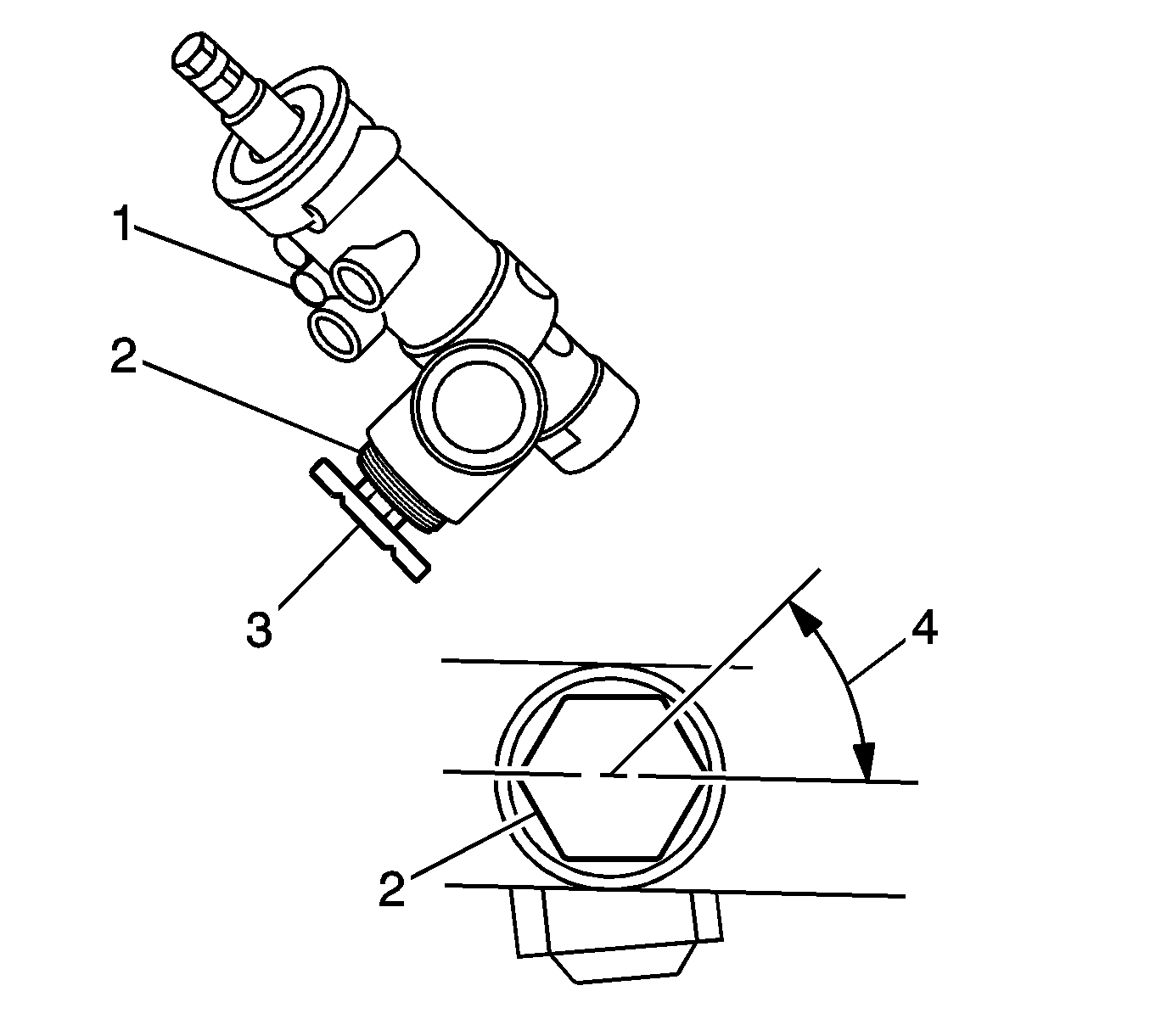
- With the rack centered in the housing, tighten the adjuster plug (2) to 10 N·m (88 lb in), then back off 40 to 50 degrees. Refer to Figure 11. Check the torque on the pinion. Maximum pinion preload torque is 4 N·m (35 lb in).
- Tighten the adjuster plug lock nut (3) firmly against the steering gear housing while holding the adjuster plug (2) stationary.
- Install a new dust cap (2) to the steering gear housing.
- If installing a new steering gear, transfer the intermediate steering shaft from the old steering gear to the new steering gear.
- If installing a new steering gear, remove the tie rod ends from the old steering gear.
- Measure the position of the adjuster nuts on the old steering gear and adjust the new nuts on the new steering gear to the same measurement.
- Install the tie rod ends on the new steering gear and tighten the adjuster nuts.
- Install the steering gear to the engine cradle in the vehicle.
- Install the two bolts attaching the steering gear to the cradle.
- Connect the pressure and return lines to the steering gear.
- Install the heat shield to the steering gear and install the attaching bolts.
- Raise the rear of the engine cradle and install the rear attaching bolts.
- Reposition the intermediate steering shaft cover (boot) and attach the steering gear.
- Connect the outer tie rod ends to the steering knuckles and install the nuts. Tighten the nuts to 10 N·m (88 lb in) and then tighten the nuts an additional 180 degrees (1/2 turn). If necessary, rotate (tighten) the nuts to align the hole and install the cotter pins.
- Install both wheel and tire assemblies.
- Lower the vehicle.
- From inside the vehicle, connect the intermediate shaft to the steering column.
- Install the driver's side insulator panel under the IP.
- Add power steering fluid as necessary and bleed the system.
- Check alignment and set toe-in as necessary.
- Install the GM Recall Identification Label.
Important: When removing the dust cap in the next step, watch for loose ball bearings that may have separated from the inner and outer pinion bearing races.
| • | If no ball bearings were found in the dust cap, proceed to the next step and replace the lower pinion bearing. |
| • | If one or more ball bearings were found loose in the dust cap, proceed to Step 31 and replace the complete steering gear assembly. |
Notice: Failure to perform the next step may result in damage to the lower pinion bearing removal tool (J 44714-1).
Important: If the stub shaft is not held in the next step, damage to the pinion teeth will occur.
Important: If the stub shaft is not held in the next step, damage to the pinion teeth will occur.
Tighten
Tighten to 30 N·m (22 lb ft).
Important: Steering gears currently available from GMSPO are verified good stock and do not require bearing inspection or replacement.
Tighten
Tighten the bolt to 48 N·m (35 lb ft).
Tighten
Tighten the nuts to 30 N·m (22 lb ft)
plus 120 degrees (or 2 flats of the nuts).
Tighten
Tighten to 80 N·m (59 lb ft).
Tighten
Tighten to 27 N·m (20 lb ft).
Tighten
Tighten to 14 N·m (124 lb in).
Tighten
Tighten to 165 N·m (122 lb ft).
Tighten
Tighten the lug nuts to 140 N·m (103 lb ft).
Tighten
Tighten the bolt to 48 N·m (35 lb ft).
1997-98 Venture, Trans Sport and Silhouette -- Lower Pinion Bearing Inspection
The following service procedure is for inspection of the lower pinion bearing and can be performed without completely removing the steering gear from the vehicle.
Important: Tool J 44714-A is required to perform this service procedure.
- From inside the vehicle, remove the driver's side insulator panel from under the instrument panel (IP).
- Disconnect the intermediate steering shaft from the steering column.
- Open the hood.
- Raise the vehicle on a suitable hoist and support.
- Support the rear of the engine frame (cradle) and remove the two rear attaching bolts.
- Lower the rear of the engine cradle as necessary to access the steering gear.
- Remove the left and right side stabilizer bar links from the lower controls arms.
- Reposition the stabilizer bar to improve access to the steering gear.
- Remove the bolts attaching the heat shield to the steering gear and remove the shield.
- Remove the two bolts that attach the steering gear to the engine cradle.
- Remove the steering gear from the cradle mounting brackets and reposition to access the lower pinion shaft dust cap.
- Remove the dust cap (3) from the steering gear housing (2) and inspect for loose ball bearings. Refer to Figure 1.
- Loosen the adjuster plug lock nut (3) and the adjuster plug (2). Refer to Figure 2. Do not remove the plug.
- While holding the stub shaft (1), remove the retaining nut (4) from the pinion shaft. Refer to Figure 1. Do not reuse the nut.
- Remove the lower retaining snap ring (1). Refer to Figure 3.
- Carefully insert the legs (1) of pinion bearing remover J 44714-1 (included in J 44714-A) between the balls in the lower pinion bearing. Refer to Figure 4.
- Assemble the center bolt (2) into the forcing screw (1) of the tool. Refer to Figure 5. Back the center bolt at least 25mm (1 in) inside the forcing screw.
- Assemble the forcing screw (2) inside the puller legs (1). Refer to Figure 6. Finger tighten the forcing screw to push the puller legs against the bearing.
- Using a 24mm wrench to hold the forcing screw, use a 17mm socket to tighten the center bolt until the bearing is removed from the gear housing. Refer to Figure 7. Do not reuse the bearing.
- Apply a small quantity of lubrication (e.g. multi-purpose grease or power steering fluid) inside the housing bore where the new bearing will be installed.
- Center the new bearing over the pinion thread. The bearing can be installed with either side facing outwards.
- Place the bearing installer (1) J 44714-2 (included in J 44714-A) over the pinion thread. Refer to Figure 8. Lightly tap with a hammer until the bearing is seated in the housing.
- Install a new snap ring. When properly installed, the large lug (1) on the snap ring must be on the right side as shown in Figure 9.
- While holding the stub shaft (1) install a new retaining nut (3) on the pinion shaft. Refer to Figure 10.
- With the rack centered in the housing, tighten the adjuster plug (2) to 10 N·m (88 lb in), then back off 40 to 50 degrees. Refer to Figure 11. Check the torque on the pinion. Maximum pinion preload torque is 4 N·m (35 lb in).
- Tighten the adjuster plug lock nut (3) firmly against the steering gear housing while holding the adjuster plug (2) stationary.
- Install a new dust cap (2) to the steering gear housing.
- Reinstall the steering gear in the engine cradle mounting brackets.
- Install the two bolts that attach the steering gear to the engine cradle.
- Install the heat shield to the steering gear and install the attaching bolts.
- Reposition the stabilizer bar.
- Install the left and right side stabilizer bar links to the lower control arms.
- Raise the rear of the engine cradle while aligning the intermediate steering shaft.
- Install the two rear engine cradle attaching bolts.
- Lower the vehicle.
- From inside the vehicle, connect the intermediate shaft to the steering column.
- Install the driver's side insulator panel under the IP.
- Check the power steering fluid and add if necessary
- Check alignment and set toe-in as necessary.
- Install the GM Recall Identification Label.
Important: When removing the dust cap in the next step, watch for loose ball bearings that may have separated from the inner and outer pinion bearing races.
| • | If no ball bearings were found in the dust cap, proceed to the next step and replace the lower pinion bearing. |
| • | If one or more ball bearings were found loose in the dust cap, proceed to the section in this recall bulletin title "Steering Gear Replacement" for the described vehicles. |
Notice: Failure to perform the next step may result in damage to the lower pinion bearing removal tool (J 44714-1).
Important: If the stub shaft is not held in the next step, damage to the pinion teeth will occur.
Important: Inspect the gear housing to ensure that no parts of the old bearing remain.
Important: If the stub shaft is not held in the next step, damage to the pinion teeth will occur.
Tighten
Tighten to 30 N·m (22 lb ft).
Tighten
Tighten the bolt to 80 N·m (59 lb ft).
Tighten
Tighten to 14 N·m (124 lb in).
Tighten
Tighten the bolts to 23 N·m (17 lb ft).
Tighten
Tighten to 165 N·m (122 lb ft).
Tighten
Tighten the bolt to 48 N·m (35 lb ft).
Steering Gear Replacement, If Required (1997-98 Venture, Trans Sport and Silhouette)
For additional information on steering gear removal, refer to the Steering section in the appropriate Service Manual.
Important: For U.S. and Canada -- All replaced steering gears are to be held until a return request is received from the GM Warranty Parts Center (WPC). Steering gears returned to the WPC will be inspected. For additional information, refer to Corporate Bulletin Number 99-00-89-019B, issued February 2002.DO NOT RETURN REPLACED STEERING GEARS TO GMSPO.
- Disconnect the pressure and return lines from the steering gear.
- Loosen the outer tie rod adjuster nuts.
- Remove both wheel and tire assemblies.
- Remove the nuts that attach the tie rod ends to the steering knuckle.
- Using the J 24319-B (outer tie rod end puller) or equivalent, separate both tie rod ends from the steering knuckles.
- Separate the intermediate steering shaft cover (boot) from the steering gear.
- Remove the steering gear from the vehicle.
- Transfer the intermediate steering shaft from the old steering gear to the new steering gear.
- Remove the tie rod ends from the old steering gear.
- Measure the position of the adjuster nuts on the old steering gear and adjust the new nuts on the new steering gear to the same measurement.
- Install the tie rod end on the new steering gear and tighten the adjuster nuts.
- Install the new steering gear in the vehicle.
- Connect the pressure and return lines to the steering gear.
- Install the steering gear in the engine cradle mounting brackets.
- Install the two bolts that attach the steering gear to the engine cradle.
- Install the heat shield to the steering gear and install the attaching bolts.
- Reposition the stabilizer bar.
- Install the left and right side stabilizer bar links to the lower control arm.
- Raise the rear of the engine cradle while aligning the intermediate steering shaft.
- Install the two rear engine cradle attaching bolts.
- Install the tie rod ends to the steering knuckles. Install the nuts.
- Install both wheel and tire assemblies.
- Lower the vehicle.
- From inside the vehicle, connect the intermediate steering shaft to the steering column.
- Install the driver's side insulator panel under the IP.
- Add power steering fluid and bleed the system.
- Check alignment and set toe-in as necessary.
- Install the GM Recall Identification Label.
Important: Steering gears currently available from GMSPO are verified good stock and do not require bearing inspection or replacement.
Tighten
Tighten the bolt to 48 N·m (35 lb ft).
Tighten
Tighten the nuts to 68 N·m (50 lb ft).
Tighten
Tighten to 27 N·m (20 lb ft).
Tighten
Tighten the bolts to 80 N·m (59 lb ft).
Tighten
Tighten the bolts to 14 N·m (124 lb in).
Tighten
Tighten the bolts to 23 N·m (17 lb ft).
Tighten
Tighten the bolts to 165 N·m (122 lb ft).
Tighten
Tighten the nuts to 30 N·m (22 lb ft),
plus 120 degrees (or 2 flats of the nut).
Tighten
Tighten the bolt to 48 N·m (35 lb ft).
1997-98 Grand Prix -- Lower Pinion Bearing Inspection
The following service procedure is for inspection of the lower pinion bearing and can be performed without completely removing the steering gear from the vehicle.
Important: Tool J 44714-A is required to perform this service procedure.
- Open the hood.
- Raise the vehicle on a suitable hoist and support.
- Remove the dust cap (3) from the steering gear housing (2) and inspect for loose ball bearings. Refer to Figure 1.
- Support the rear of the engine frame (cradle) and remove the two rear attaching bolts.
- Remove the left and right side stabilizer bar links from the lower control arms.
- Reposition the stabilizer bar as necessary to improve access to the steering gear.
- Remove the two bolts that attach the steering gear to the engine cradle.
- Remove the bolt and separate the intermediate steering shaft from the steering gear.
- Lower the rear of the engine cradle as necessary to access the steering gear.
- Remove the steering gear from the engine cradle mounting brackets and reposition to access the adjuster plug lock nut and the adjuster plug. Do not remove the plug.
- Loosen the adjuster plug lock nut (3) and the adjuster plug (2). Refer to Figure 2. Do not remove the plug.
- While holding the stub shaft (1), remove the retaining nut (4) from the pinion shaft. Refer to Figure 1. Do not reuse the nut.
- Remove the lower retaining snap ring (1). Refer to Figure 3.
- Carefully insert the legs (1) of pinion bearing remover J 44714-1 (included in J 44714-A) between the balls in the lower pinion bearing. Refer to Figure 4.
- Assemble the center bolt (2) into the forcing screw (1) of the tool. Refer to Figure 5. Back the center bolt at least 25mm (1 in) inside the forcing screw.
- Assemble the forcing screw (2) inside the puller legs (1). Refer to Figure 6. Finger tighten the forcing screw to push the puller legs against the bearing.
- Using a 24mm wrench to hold the forcing screw, use a 17mm socket to tighten the center bolt until the bearing is removed from the gear housing. Refer to Figure 7. Do not reuse the bearing.
- Apply a small quantity of lubrication (e.g. multi-purpose grease or power steering fluid) inside the housing bore where the new bearing will be installed.
- Center the new bearing over the pinion thread. The bearing can be installed with either side facing outwards.
- Place the bearing installer (1) J 44714-2 (included in J 44714-A) over the pinion thread. Refer to Figure 8. If necessary, use the extension included with the installer. Lightly tap with a hammer until the bearing is seated in the housing.
- Install a new snap ring. When properly installed, the large lug (1) on the snap ring must be on the right side as shown in Figure 9.
- While holding the stub shaft (1) install a new retaining nut (3) on the pinion shaft. Refer to Figure 10.
- With the rack centered in the housing, tighten the adjuster plug (2) to 10 N·m (88 lb in), then back off 40 to 50 degrees. Refer to Figure 11. Check the torque on the pinion. Maximum pinion preload torque is 4 N·m (35 lb in).
- Tighten the adjuster plug lock nut (3) firmly against the steering gear housing while holding the adjuster plug (2) stationary.
- Install a new dust cap (2) to the steering gear housing.
- Install the steering gear in the engine cradle mounting brackets.
- Install the two bolts that attach the steering gear to the engine cradle.
- Raise the rear of the engine cradle and install the rear attaching bolts.
- Connect the intermediate steering shaft to the steering gear and install the bolt.
- Reposition the stabilizer bar.
- Install the left and right side stabilizer bar links to the lower control arm.
- Lower the vehicle.
- Check the power steering fluid and add if necessary
- Check the alignment and set toe-in as necessary.
- Install the GM Recall Identification Label.
Important: When removing the dust cap in the next step, watch for loose ball bearings that may have separated from the inner and outer pinion bearing races.
| • | If no ball bearings were found in the dust cap, proceed to the next step and replace the lower pinion bearing. |
| • | If one or more ball bearings were found loose in the dust cap, proceed to the section in this recall bulletin title "Steering Gear Replacement" for the described vehicles. |
Notice: Failure to perform the next step may result in damage to the lower pinion bearing removal tool (J 44714-1).
Important: If the stub shaft is not held in the next step, damage to the pinion teeth will occur.
Important: Placement of a block of wood between the steering gear housing and the transmission case will help to support the steering gear in the next step.
Important: Inspect the gear housing to ensure that no parts of the old bearing remain.
Important: If the stub shaft is not held in the next step, damage to the pinion teeth will occur.
Tighten
Tighten to 30 N·m (22 lb ft).
Tighten
Tighten the bolt to 80 N·m (59 lb ft).
Tighten
Tighten to 180 N·m (133 lb ft).
Tighten
Tighten the bolt to 48 N·m (35 lb ft).
Tighten
Tighten to 23 N·m (17 lb ft).
Steering Gear Replacement, If Required -- 1997-98 Grand Prix
For additional information on steering gear removal, refer to the Steering section in the appropriate Service Manual.
Important: For U.S. and Canada -- All replaced steering gears are to be held until a return request is received from the GM Warranty Parts Center (WPC). Steering gears returned to the WPC will be inspected. For additional information, refer to Corporate Bulletin Number 99-00-89-019B, issued February 2002.DO NOT RETURN REPLACED STEERING GEARS TO GMSPO.
- Remove the bolt and separate the intermediate steering shaft from the steering gear.
- Support the rear of the engine frame (cradle) and remove the two rear attaching bolts.
- Remove the left and right side stabilizer bar links from the lower control arms.
- Reposition the stabilizer bar as necessary to improve access to the steering gear.
- Remove the two bolts that attach the steering gear to the engine cradle.
- Lower the rear of the engine cradle as necessary to access the steering gear.
- Loosen the outer tie rod end adjuster nuts.
- Remove both wheel and tire assemblies.
- Remove the nuts that attach the tie rod ends to the steering knuckles.
- Using the J 24319-B (outer tie rod end puller) or equivalent, separate the tie rod ends from the knuckles.
- Disconnect the pressure and return lines from the steering gear.
- On GT and GTP models, disconnect the electrical connector from the steering gear.
- Remove the steering gear from the vehicle.
- Remove the tie rod ends from the old steering gear.
- Measure the position of the adjuster nuts on the old steering gear and adjust the new nuts on the new steering gear to the same measurement.
- Install the tie rod ends on the new steering gear and tighten the adjuster nuts.
- Install the new steering gear in the engine cradle mounting brackets.
- On GT and GTP models, connect the electrical connector for the steering gear.
- Install the two bolts that attach the steering gear to the engine cradle.
- Connect the pressure and return lines to the steering gear.
- Install the tie rod ends to the steering knuckles. Install the retaining nuts.
- Raise the rear of the engine cradle and install the two rear attaching bolts.
- Install the intermediate steering shaft to the steering gear and install the bolt.
- Reposition the stabilizer bar.
- Install the left and right side stabilizer bar links to the lower control arms.
- Install both wheel and tire assemblies.
- Lower the vehicle.
- Add power steering fluid and bleed the system.
- Check the alignment and set toe-in as necessary.
- Install the GM Recall Identification Label.
Important: Steering gears currently available from GMSPO are verified good stock and do not require bearing inspection or replacement.
Tighten
Tighten the nuts to 68 N·m (50 lb ft).
Tighten
Tighten to 80 N·m (59 lb ft).
Tighten
Tighten to 27 N·m (20 lb ft).
Tighten
Tighten the nuts to 30 N·m (22 lb ft)
plus 120 degrees (or 2 flats of the nut).
Tighten
Tighten to 180 N·m (133 lb ft).
Tighten
Tighten to 48 N·m (35 lb ft).
Tighten
Tighten the nuts to 23 N·m (17 lb ft).
Tighten
Tighten the lug nuts to 140 N·m (103 lb ft).
1996-98 Cavalier and Sunfire - Lower Pinion Bearing Inspection
The following service procedure is for inspection of the lower pinion bearing and can be performed without completely removing the steering gear from the vehicle.
Important: Tool J 44714-A is required to perform this service procedure.
- Open the hood.
- Raise the vehicle on a suitable hoist and support.
- Remove the two bolts attaching the steering gear to the engine frame (cradle).
- Release the brake pipe from the retainers at three locations on the engine cradle.
- Remove the steering gear from the engine cradle mounting brackets and reposition to access the lower pinion shaft dust cap.
- Remove the dust cap (3) from the steering gear housing (2) and inspect for loose ball bearings. Refer to Figure 1.
- Loosen the adjuster plug lock nut (3) and the adjuster plug (2). Refer to Figure 2. Do not remove the plug.
- While holding the stub shaft (1), remove the retaining nut (4) from the pinion shaft. Refer to Figure 1. Do not reuse the nut.
- Remove the lower retaining snap ring (1). Refer to Figure 3.
- Carefully insert the legs (1) of pinion bearing remover J 44714-1 (included in J 44714-A) between the balls in the lower pinion bearing. Refer to Figure 4.
- Assemble the center bolt (2) into the forcing screw (1) of the tool. Refer to Figure 5. Back the center bolt at least 25mm (1 in) inside the forcing screw.
- Assemble the forcing screw (2) inside the puller legs (1). Refer to Figure 6. Finger tighten the forcing screw to push the puller legs against the bearing.
- Using a 24mm wrench to hold the forcing screw, use a 17mm socket to tighten the center bolt until the bearing is removed from the gear housing. Refer to Figure 7. Do not reuse the bearing.
- Apply a small quantity of lubrication (e.g. multi-purpose grease or power steering fluid) inside the housing bore where the new bearing will be installed.
- Center the new bearing over the pinion thread. The bearing can be installed with either side facing outwards.
- Place the bearing installer (1) J 44714-2 (included in J 44714-A) over the pinion thread. Refer to Figure 8. If necessary, use the extension J 44714-3 included with the installer. Lightly tap with a hammer until the bearing is seated in the housing.
- Install a new snap ring. When properly installed, the large lug (1) on the snap ring must be on the right side as shown in Figure 9.
- While holding the stub shaft (1) install a new retaining nut (3) on the pinion shaft. Refer to Figure 10.
- With the rack centered in the housing, tighten the adjuster plug (2) to 10 N·m (88 lb in), then back off 40 to 50 degrees. Refer to Figure 11. Check the torque on the pinion. Maximum pinion preload torque is 4 N·m (35 lb in).
- Tighten the adjuster plug lock nut (3) firmly against the steering gear housing while holding the adjuster plug (2) stationary.
- Install a new dust cap (2) to the steering gear housing.
- Reinstall the steering gear in the engine cradle mounting brackets.
- Reattach the brake pipe to the retainers on the engine cradle.
- Install the two bolts that attach the steering gear to the cradle.
- Lower the vehicle.
- Check the power steering fluid and add if necessary
- Install the GM Recall Identification Label.
Important: When removing the dust cap in the next step, watch for loose ball bearings that may have separated from the inner and outer pinion bearing races.
| • | If no ball bearings were found in the dust cap, proceed to the next step and replace the lower pinion bearing. |
| • | If one or more ball bearings were found loose in the dust cap, proceed to the section in this recall bulletin title "Steering Gear Replacement" for the described vehicles. |
Notice: Failure to perform the next step may result in damage to the lower pinion bearing removal tool (J 44714-1).
Important: If the stub shaft is not held in the next step, damage to the pinion teeth will occur.
Important: Inspect the gear housing to ensure that no parts of the old bearing remain.
Important: If the stub shaft is not held in the next step, damage to the pinion teeth will occur.
Tighten
Tighten to 30 N·m (22 lb ft).
Tighten
Tighten the bolt to 120 N·m (88 lb ft).
Important: It is NOT necessary to check alignment or toe-in when performing this procedure because the position of the engine frame (cradle) to the body has not been disturbed.
Steering Gear Replacement, If Required -- 1996-98 Cavalier and Sunfire
Important: For U.S. and Canada -- All replaced steering gears are to be held until a return request is received from the GM Warranty Parts Center (WPC). Steering gears returned to the WPC will be inspected. For additional information, refer to Corporate Bulletin Number 99-00-89-019B, issued February 2002.DO NOT RETURN REPLACED STEERING GEARS TO GMSPO.
- Remove both wheel and tire assemblies.
- Remove the nuts that attach the tie rod ends to the steering knuckle.
- Using the J 24319-B (outer tie rod end puller) or equivalent, separate the tie rod ends from the knuckles.
- Support the rear of the engine frame (cradle) and remove the six rear attaching bolts.
- Loosen the front cradle to body attaching bolts. Do not remove the bolts.
- Lower the rear of the engine cradle as necessary to access the steering gear.
- Disconnect the pressure and return lines from the steering gear.
- Remove the bolt and separate the intermediate steering shaft from the steering gear.
- Remove the steering gear from the vehicle.
- If necessary, transfer the mounting grommet(s) and bushing(s) from the old steering gear to the new steering gear. Note that the labor time allowance includes the time needed for transferring these parts.
- Remove the tie rod ends from the old steering gear.
- Measure the position of the adjuster nuts on the old steering gear and adjust the new nuts on the new steering gear to the same measurement.
- Install the tie rod ends on the new steering gear and tighten the adjuster nuts.
- Install the new steering gear in the engine cradle mounting brackets.
- Install the two bolts that attach the steering gear to the engine cradle.
- Connect the pressure and return lines to the steering gear.
- Raise the rear of the engine cradle while aligning the intermediate steering shaft.
- Install the six rear engine cradle bolts.
- Tighten the front engine cradle to body bolts.
- Install the intermediate steering shaft to the steering gear and install the bolt.
- Reposition the brake pipe to the retainers on the engine cradle.
- Install the tie rod ends to the steering knuckles. Install the retaining nuts.
- Install both wheel and tire assemblies.
- Lower the vehicle.
- Add power steering fluid and bleed the system.
- Check the alignment and set toe-in as necessary.
- Install the GM Recall Identification Label.
Important: Steering gears currently available from GMSPO are verified good stock and do not require bearing inspection or replacement.
Tighten
Tighten the nuts to 68 N·m (50 lb ft).
Tighten
Tighten to 120 N·m (88 lb ft).
Tighten
Tighten to 27 N·m (20 lb ft).
Tighten
Tighten to 110 N·m (81 lb ft).
Tighten
Tighten to 110 N·m (81 lb ft).
Tighten
Tighten to 22 N·m (16 lb ft).
Tighten
Tighten the nuts to 45 N·m (33 lb ft).
Tighten
Tighten the lug nuts to 140 N·m (103 lb ft).
Figure 1
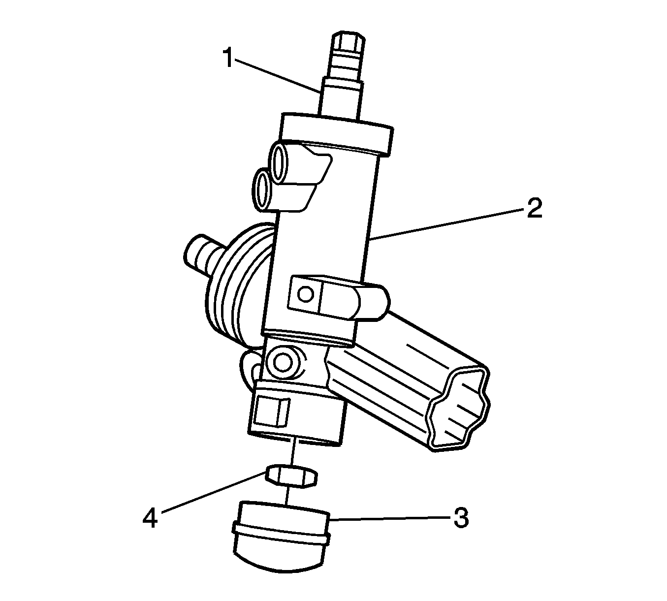
Figure 2
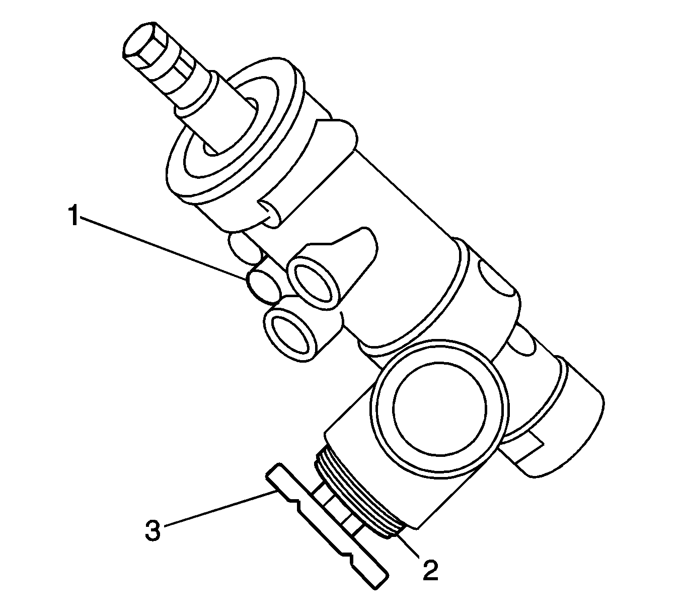
Figure 3
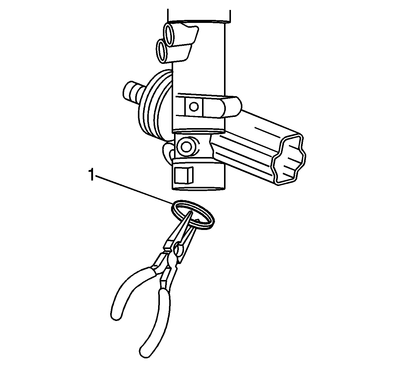
Figure 4
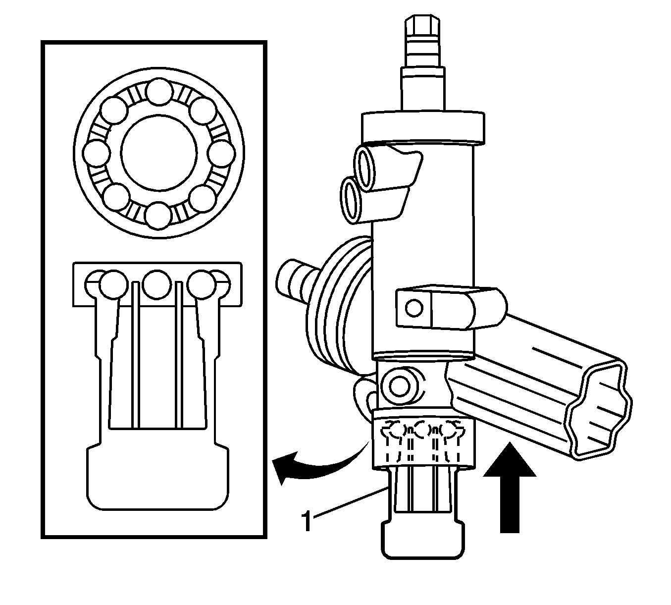
Figure 5
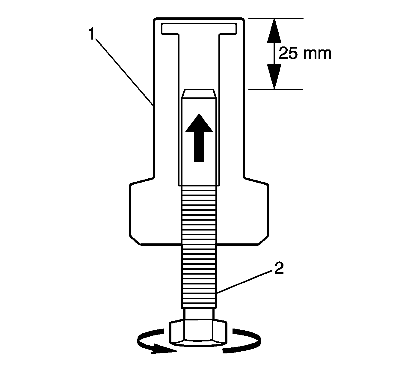
Figure 6
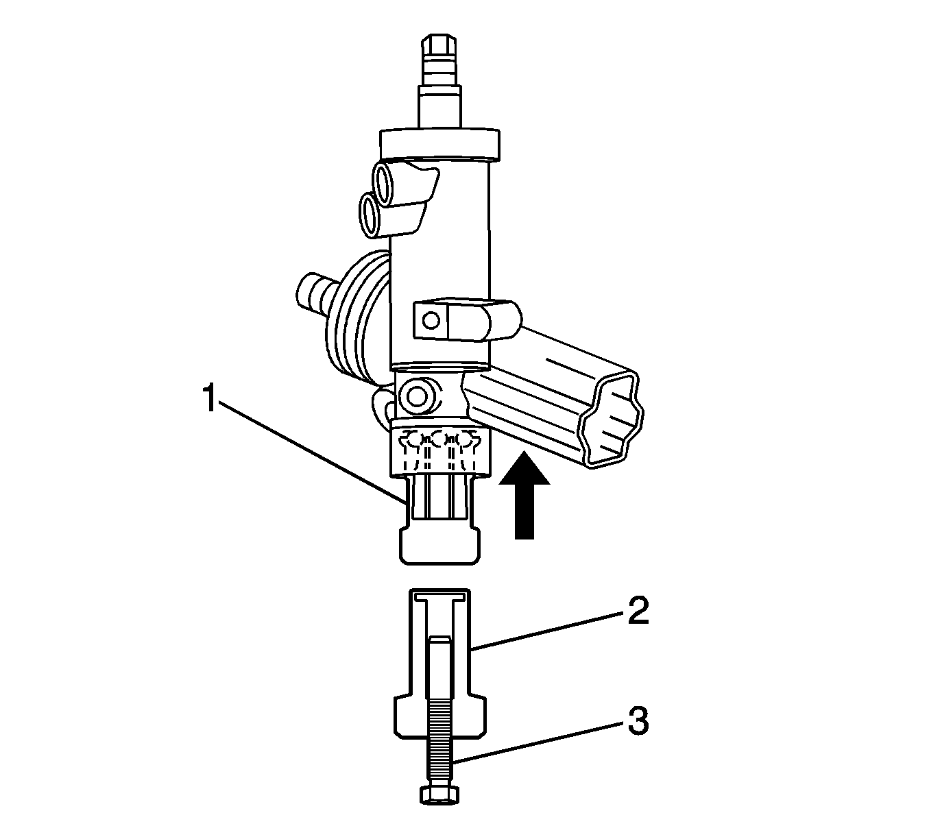
Figure 7
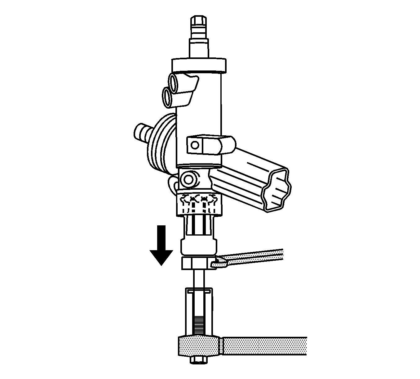
Figure 8
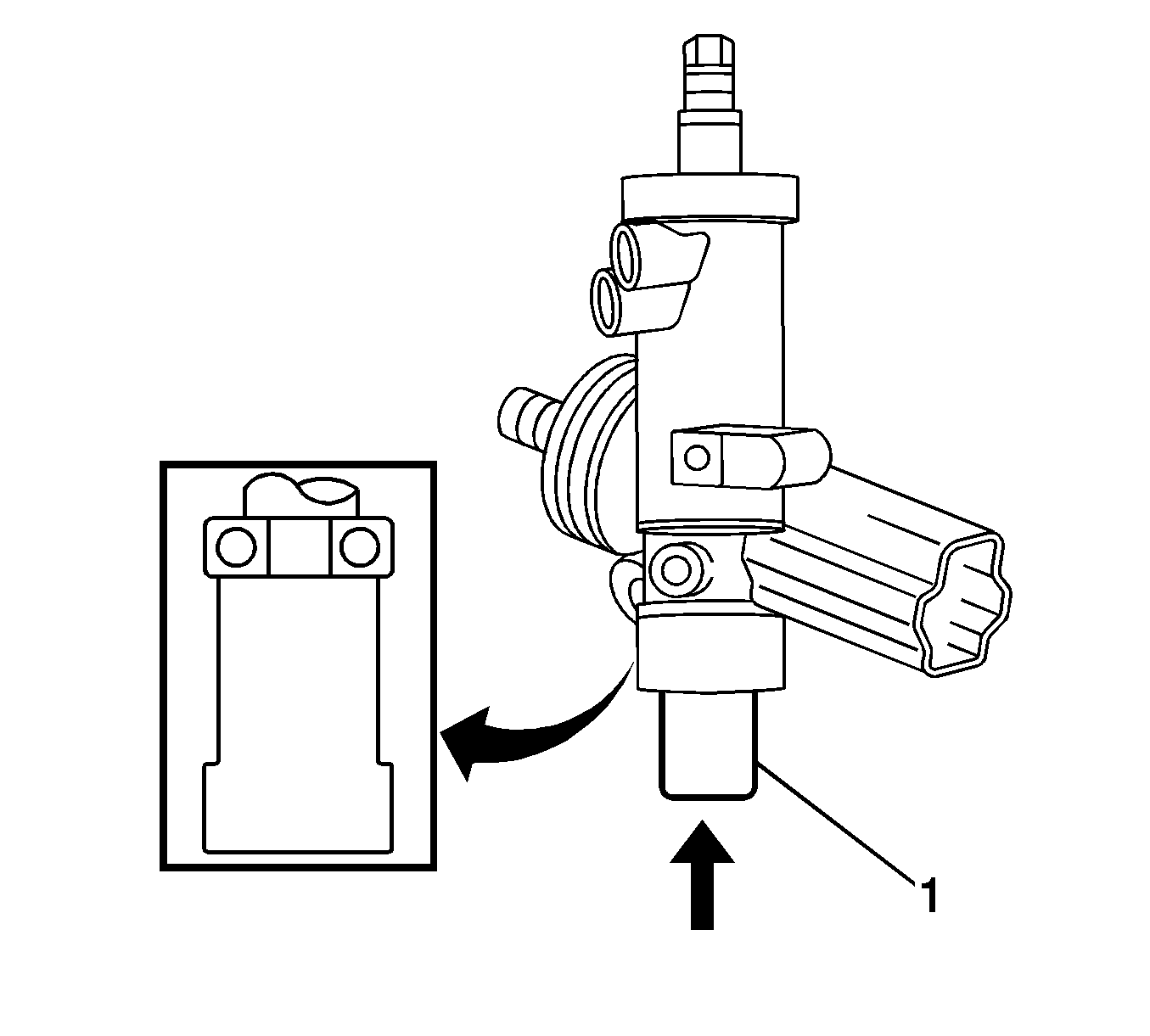
Figure 9
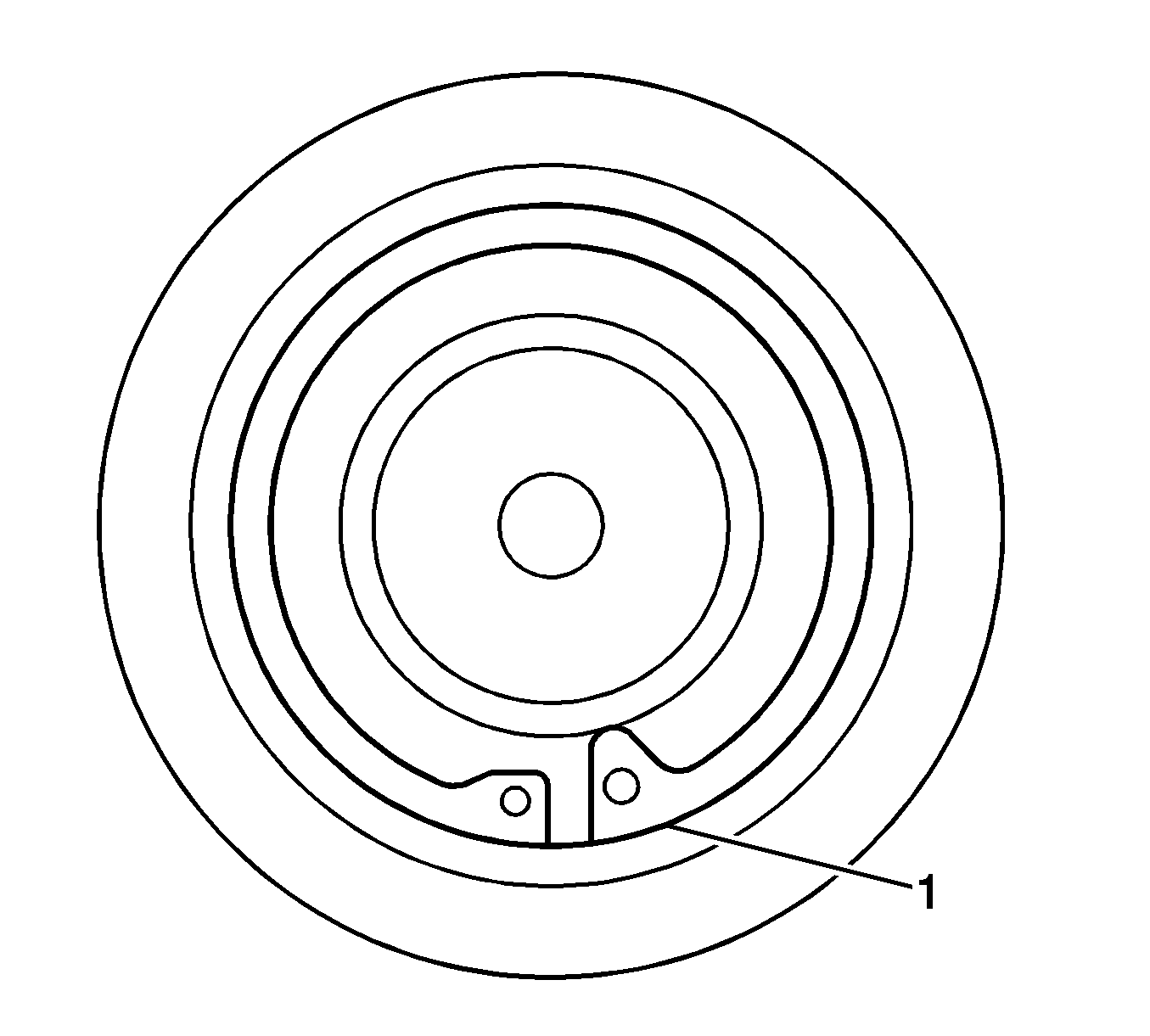
Figure 10
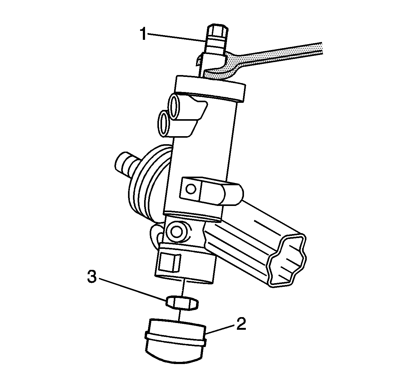
Figure 11
Recall Identification Label -- For US and IPC
Place a Recall Identification Label on each vehicle corrected in accordance with the instructions outlined in this Product Recall Bulletin. Each label provides a space to include the recall number and the five (5) digit dealer code of the dealer performing the recall service. This information may be inserted with a typewriter or a ball point pen.
Put the Recall Identification Label on a clean and dry surface of the radiator core support in an area that will be visible to people servicing the vehicle. When installing the Recall Identification Label, be sure to pull the tab to allow the adhesion of the clear protective covering. Additional Recall Identification Labels for US dealers can be obtained from Dealer Support Materials by either ordering on the web from DWD Store, gm-dealerworld.com, or calling 1-866-700-0001 (Monday-Friday, 8:00 am to 5:00 pm EST). Ask for Item Number S-1015 when ordering.
Additional Recall Identification Labels for IPC dealers can be obtained from your Regional Marketing Office.
Recall Identification Label -- For Canada
Place a Recall Identification Label on each vehicle corrected in accordance with the instructions outlined in this Product Recall Bulletin. Each label provides a space to include the recall number and the five (5) digit dealer code of the dealer performing the recall service. This information may be inserted with a typewriter or a ball point pen.
Put the Recall Identification Label on a clean and dry surface of the radiator core support in an area that will be visible to people servicing the vehicle. Additional Recall Identification Labels for Canadian dealers can be obtained from DGN by calling 1-800-668-5539 (Monday-Friday, 8:00 am to 5:00 pm EST). Ask for Item Number GMP 91 when ordering.
Customer Reimbursement
Customer requests for reimbursement of previously paid repairs to replace the power steering gear lower pinion bearing or steering gear due to lower pinion bearing separation are to be submitted by January 31, 2004 (this time limit may be longer depending on the law in your state/province/country).
All reasonable customer paid receipts should be considered for reimbursement. The amount to be reimbursed will be limited to the amount the repair would have cost if completed by an authorized General Motors dealer.
When a customer requests reimbursement, they must provide the following:
| • | Proof of ownership at time of repair. |
| • | Original paid receipt confirming the amount of unreimbursed repair expense(s), a description of the repair, and the person or entity performing the repair. |
Customer from the States of California, Connecticut, Virginia and Wisconsin must submit requests for reimbursement directly to (Divisions) per instructions in the owner letter.
Claims for customer reimbursement on previously paid are to be submitted as required by WINS.
Important: Refer to the GM Service Policies and Procedures Manual, section 1.6.2. for specific procedures regarding customer reimbursement verification.
Claim Information
Submit a Product Recall Claim with the information indicated below:
Repair Performed | Part Count | Part No. | Parts Allow | CC-FC | Labor Op | Labor Hours | Net Item |
|---|---|---|---|---|---|---|---|
Inspect & Replace Lower Pinion Bearing (Inc. Setting Toe-In, If Instructed In Service Procedure) | 1 | -- | ** | MA-96 | V0948 |
| *** |
1996 Lumina APV, Trans Sport, Silhouette |
|
|
|
|
| 2.2* |
|
1997-98 Venture, Trans Sport, Silhouette |
|
|
|
|
| 2.1* |
|
Cavalier, Sunfire |
|
|
|
|
| 0.6* |
|
Grand Prix |
|
|
|
|
| 1.8* |
|
Inspect Lower Pinion Bearing & Replace Steering Gear (Inc. Setting Toe-In) | 1 | -- | **** | MA-96 | V0949 |
| *** |
1996 Lumina APV, Trans Sport, Silhouette |
|
|
|
|
| 2.2* |
|
1997-98 Venture, Trans Sport, Silhouette |
|
|
|
|
| 2.6* |
|
Cavalier, Sunfire |
|
|
|
|
| 2.2* |
|
Grand Prix |
|
|
|
|
| 2.3* |
|
Customer Reimbursement (the recall must still be performed on the vehicle) |
|
|
| MA-96 | V0950 | 0.2 | ***** |
* -- For Program Administrative Allowance, add 0.1 hour to the "Labor Hours". ** -- The "Parts Allowance" should be the sum total of the current GMSPO Dealer net price plus applicable Mark-Up or Landed Cost Mark-Up (for IPC) for the lower pinion bearing needed to complete the repair. *** -- The amount identified in the "Net Item" column should represent the sum total of the current GMSPO Dealer net price plus applicable Mark-Up or Landed Cost Mark-Up (for IPC) for the actual amount of power steering fluid needed to complete the repair. **** -- The "Parts Allowance" should be the sum total of the current GMSPO Dealer net price plus applicable Mark-Up or Landed Cost Mark-Up (for IPC) for the steering gear needed to complete the repair. ***** -- The amount identified in the "Net Item" column should represent the dollar amount reimbursed to the customer. | |||||||
Refer to the General Motors WINS Claims Processing Manual for details on Product Recall Claim Submission.
Customer Notification -- For US and Canada
Customers will be notified of this recall on their vehicles by General Motors (see copy of customer letter included with this bulletin).
Customer Notification -- For IPC
Letters will be sent to known owners of record located within areas covered by the US National Traffic and Motor Vehicle Safety Act. For owners outside these areas, dealers should notify customers using the attached sample letter.
Dealer Recall Responsibility -- For US and IPC (US States, Territories, and Possessions)
The US National Traffic and Motor Vehicle Safety Act provides that each vehicle which is subject to a recall of this type must be adequately repaired within a reasonable time after the customer has tendered it for repair. A failure to repair within sixty days after tender of a vehicle is prima facie evidence of failure to repair within a reasonable time. If the condition is not adequately repaired within a reasonable time, the customer may be entitled to an identical or reasonably equivalent vehicle at no charge or to a refund of the purchase price less a reasonable allowance for depreciation. To avoid having to provide these burdensome remedies, every effort must be made to promptly schedule an appointment with each customer and to repair their vehicle as soon as possible. In the recall notification letters, customers are told how to contact the US National Highway Traffic Safety Administration if the recall is not completed within a reasonable time.
Dealer Recall Responsibility -- All
All unsold new vehicles in dealers' possession and subject to this recall MUST be held and inspected/repaired per the service procedure of this recall bulletin BEFORE customers take possession of these vehicles.
Dealers are to service all vehicles subject to this recall at no charge to customers, regardless of mileage, age of vehicle, or ownership, from this time forward.
Customers who have recently purchased vehicles sold from your vehicle inventory, and for which there is no customer information indicated on the dealer listing, are to be contacted by the dealer. Arrangements are to be made to make the required correction according to the instructions contained in this bulletin. This could be done by mailing to such customers a copy of the customer letter accompanying this bulletin. Recall follow-up cards should not be used for this purpose, since the customer may not as yet have received the notification letter.
In summary, whenever a vehicle subject to this recall enters your vehicle inventory, or is in your dealership for service in the future, please take the steps necessary to be sure the recall correction has been made before selling or releasing the vehicle.
January, 2003Dear General Motors Customer:
This notice is sent to you in accordance with the requirements of the National Traffic and Motor Vehicle Safety Act.
Reason For This Recall
General Motors has decided that a defect which relates to motor vehicle safety exists in certain 1996, 1997, and 1998 model year Chevrolet Cavalier; 1996 model year Chevrolet Lumina APV; 1997 and 1998 model year Chevrolet Venture; 1996, 1997, and 1998 model year Pontiac Sunfire, Trans Sport; 1997 and 1998 model year Pontiac Grand Prix; and 1996, 1997, and 1998 model year Oldsmobile Silhouette vehicles. Some of these vehicles may have a condition where the lower pinion bearing in the power steering gear may separate. Most reports indicate the driver experienced an intermittent loss of power steering assist when making left turns, usually at low speeds. Power assist is normal in right hand turns. When trying to turn left, some drivers could experience higher resistance or, in a few cases, assist towards the right. If this happens while the vehicle is moving, a crash could result.
What Will Be Done
Your GM dealer will inspect the condition of the lower pinion bearing in the rack and pinion steering gear assembly and replace the lower pinion bearing, or in a few cases, replace the rack and pinion steering gear assembly. This service will be performed for you at no charge .
How Long Will The Repair Take?
The length of time required to inspect and replace the lower pinion bearing is approximately 30 minutes for the Cavalier and Sunfire, and 2 hours for all other vehicles. A small number of vehicles will require replacement of the rack and pinion steering gear assembly, which will take approximately 2 to 2 ½ hours to perform the service correction. . Additional time may be required to schedule and process your vehicle. If you dealer has a large number of vehicles awaiting service, this additional time may be significant. Please ask your dealer if you wish to know how much additional time will be needed to schedule, process and repair your vehicle.
Contacting Your Dealer
Please contact your dealer as soon as possible to arrange a service date. Parts are available and instructions for making this correction have been sent to your dealer.
Your dealer is best equipped to obtain parts and provide services to correct your vehicle as promptly as possible. Should your dealer be unable to schedule a service date within a reasonable time, you should contact the appropriate Customer Assistance Center at the number listed below:
Division | Number | Deaf, Hearing Impaired, or Speech Impaired* |
|---|---|---|
Chevrolet | 1-800-222-1020 | 1-800-833-2438 |
Pontiac | 1-800-762-2737 | 1-800-833-7668 |
Oldsmobile | 1-800-442-6537 | 1-800-833-6537 |
GMODC | (905)644-4112 |
|
Puerto Rico - English | 1-800-496-9992 |
|
Puerto Rico - Español | 1-800-496-9993 |
|
Virgin Islands | 1-800-496-9994 |
|
* Utilizes Telecommunication Devices for the Deaf/Text Telephones (TDD/TTY) | ||
If, after contacting the appropriate customer assistance center, you are still not satisfied that we have done our best to remedy this condition without charge and within a reasonable time, you may wish to write the Administrator, National Highway Traffic Safety Administration, 400 Seventh Street SW, Washington, DC 20590 or call 1-888-327-4236.
Customer Reply Card
The attached customer reply card identifies your vehicle. Presentation of this card to your dealer will assist in making the necessary correction in the shortest possible time. If you no longer own this vehicle, please let us know by completing the attached and mailing it in the postage paid envelope.
Reimbursement
(Statement for all states except as shown below)
If you have already paid for some or all of the cost to replace the power steering gear lower pinion bearing or the rack and pinion steering gear due to lower pinion bearing separation, and you have not received reimbursement under a Vehicle Service Contract, you should contact your dealer to seek reimbursement. Please provide your dealer with your original paid receipts or invoices verifying the repair, the amount charged, proof of payment, the date of payment of those charges, and proof of ownership of the vehicle at the time of the repair. Your request for reimbursement, including the information and documents mentioned above, must be received by your dealer by January 31, 2004.
(Statement for California, Connecticut, Virginia, and Wisconsin)
If you have already paid for some or all of the cost to replace the power steering gear lower pinion bearing or the rack and pinion steering gear due to lower pinion bearing separation, and you have not received reimbursement under a Vehicle Service Contract, you should write to your divisional specific address to seek reimbursement. Please provide your dealer with your original paid receipts or invoices verifying the repair, the amount charged, proof of payment, the date of payment of those charges, and proof of ownership of the vehicle at the time of the repair. This information must be provided within two (2) years after the date on which you paid for the repair.
We are sorry to cause you this inconvenience; however, we have taken this action in the interest of your safety and continued satisfaction with our products.
General Motors Corporation
Enclosure
