CAMPAIGN: MASTER CYLINDER BRAKE PROPORTIONER

Models/Years 1983 Cutlass Cieras, Omegas and Firenzas
CONDITION
General Motors has determined that a defect which relates to motor vehicle safety exists on some 1983 Cutlass Ciera, Omega and Firenza cars. The brake proportioner valves used on some of these vehicles may break and separate from the master cylinder. This would result in a dual braking system; part of the system will still work and allow the vehicle to be stopped, but over a greater distance. Partial loss of the brake system at a time when minimum stopping distance is required could result in a vehicle crash without prior warning.
VEHICLES INVOLVED
Involved are certain 1983 Cutlass Cieras, Omegas and Firenzas within the following serial numbers.
SERIES ASSEMBLY PLANT BEGINNING UP TO & INCLUDING ------ --------------- --------- ----------------- Cutlass Ciera Doraville DD334506 DD373389 DD376496 DD377072 DD377632 DD378204 DD384484 DD385283
Omega Willow Run DW311071 DW324706 DW324963 DW326249 DW327012 DW327771 DW328852 DW329505 DW331770 DW332404 DW332842 DW333260 Firenza Leeds DK305993 DK315268 DK318264 DK319692
DEALER ACTION
To prevent the possibility of this condition occurring on vehicles involved, dealers are to inspect to determine if a vehicle has suspect proportioner valves as instructed in the Service Procedure of this bulletin. ALL suspect valves are to be replaced.
Dealers are to service all vehicles subject to this campaign at no charge to owners, regardless of mileage, age of vehicle, or ownership, from this time forward.
Whenever a vehicle subject to this campaign is taken into your new or used vehicle inventory, or it is in your dealership for service in the future, you should take the steps to be sure the campaign correction has been made before reselling or releasing the vehicle.
Owners of vehicles recently sold from your new vehicle inventory are to be contacted by the dealer, and arrangements made to make the required modification according to instructions contained in this bulletin.
SERVICE PROCEDURE
PART I Inspection of Proportioner Valves ---------------------------------
1. Open vehicle hood and cover left-front fender.
2. It may be necessary to clean the ends of the front and rear brake proportioner valves located in the master cylinder for inspection. If this is required, wipe valves clean using brake fluid. Do not use a solvent to clean the valves, as it could enter the small notches (vents) of valves and cuase damage to the internal seals of the valves.
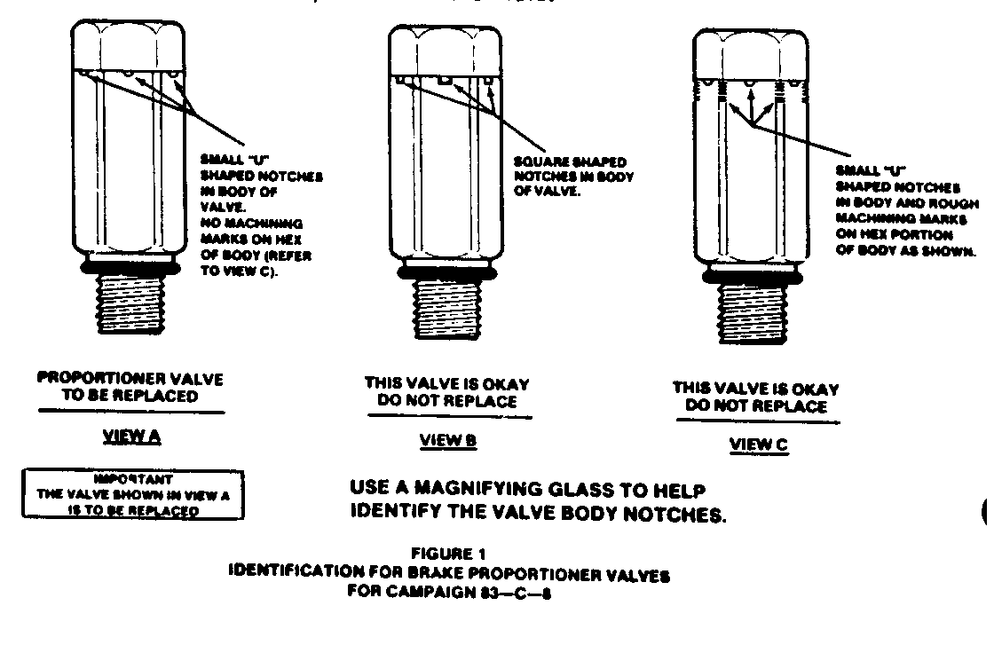
3. Inspect the front and rear proportioner valves to determine if either one or both of the valves need to be replaced. Refer to Figure 1. Use a magnifying glass to identify the valves. Proportioner valves from three different sources were used interchangeably; therefore, both front and rear valves will not require replacement in all cases.
4. Replace all proportioner valves, as instructed in Part II of this procedure, that are o design shown in View A of Figure 1. If the valve identification cannot be accurately determined, or there is a question on identification, valve(s) should be replaced.
Special care should be taken to insure that specified torque values are used when installing new proportioner valves.
5. If valves are the design shown in View B or View C of Figure 1, no further action is required except to install a campaign identification label as instructed in Part III of this procedure.
PART II
Replacement of Proportioner Valve
1. Refer to Parts Information of this bulletin to obtain correct part number proportioner valve(s) for vehicle.
2. Place material under proportioner valve connections to protect under hood parts from brake fluid.
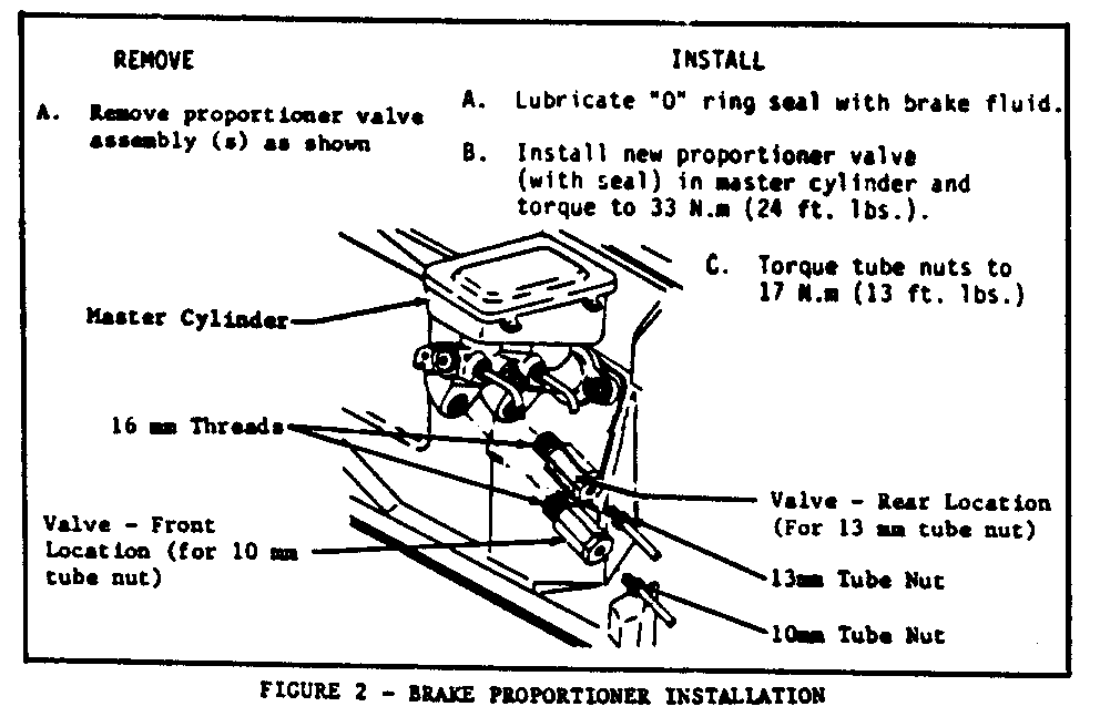
3. Refer to Figure 2 for valve replacement procedure.
4. Bleed master cylinder and proportioner valve connections as follows:
a. If the car is equipped with power brakes, remove the vacuum reserve by applying the brakes several times.
b. After installing new valve(s), reconnect all brake pipe connectors.
c. Fill the master cylinder reserviors with brake fluid and keep at least one-half full of fluid during the bleeding operation.
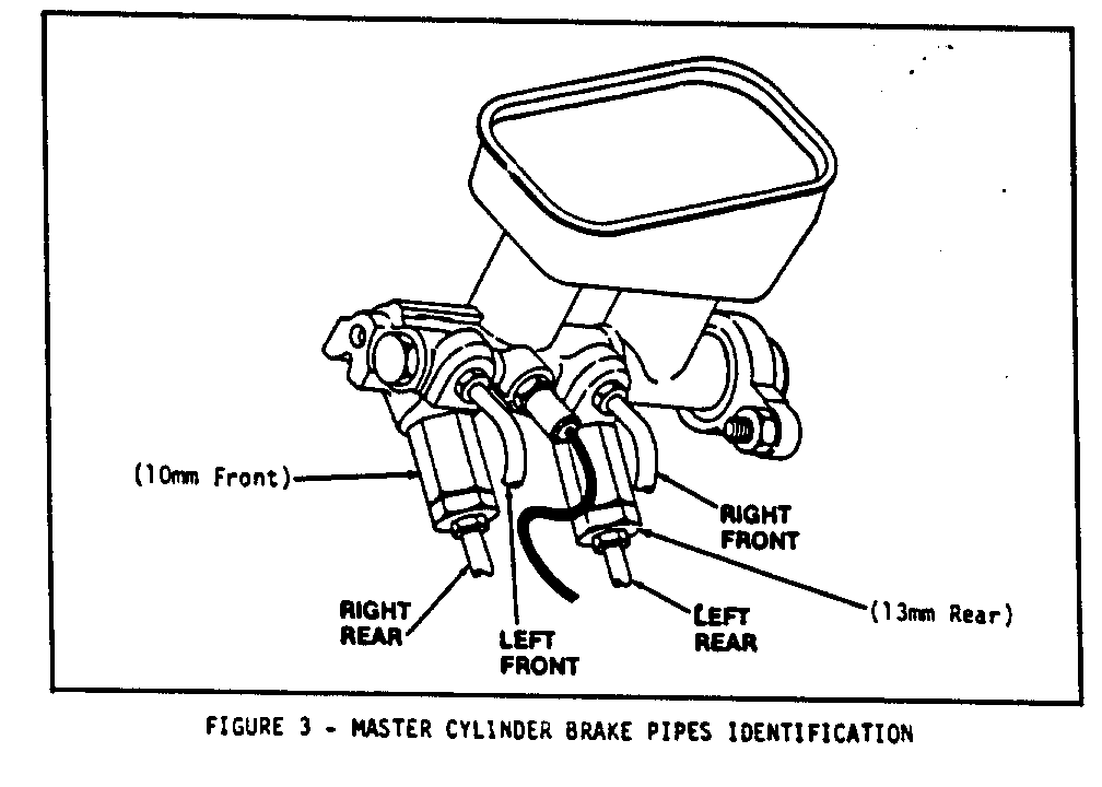
d. Remove left front pipe connector. Refer to Figure 3. When brake fluid begins to flow from left front master cylinder port, reconnect left front brake pipe and tighten to specified torque.
e. Slowly apply brake pedal until firm.
f. Loosen left front brake pipe connector to purge air. Retighten connector and slowly release brake pedal. Wait 15 seconds.
g. Repeat (e) and (f) until all air is purged. (Important: Complete (g) before attempting (h) and (i).)
h. Repeat (e) and now loosen right front brake pipe connector to purge air. When brake fluid begins to flow from connector, retighten connector to specified torque and slowly release brake pedal. Wait 15 seconds. Refer to Figure 3.
i. Repeat (h) until all air is purged.
5. Check the brake pedal for "sponginess" and brake warning light for indication of unbalanced pressure. Repeat bleeding operation to correct. Do not move car until a firm brake pedal is obtained.
6. Tighten all tube nuts to specified torque and correct any leaks, if required.
7. Fill master cylinder.
8. Install a campaign identification label.
PART III
Installation of Campaign Identification Label
After the above has been completed, install a campaign identificaiton label as follows:
Each label provides a space to include the campaign number, the five (5) digit Dealer Code of the dealer performing the campaign service, and the date vehicle was campaigned. This information may be inserted with a typewriter or ballpoint pen. When installing label, clean the surface of the fan guard and apply the campaign label where it is readily visible.
PARTS INFORMATION
The parts for this campaign are to be obtained from WDDGM as required. Refer to chart to obtain correct valve for a vehicle.
PART NUMBER & (I.D. CODE ON VALVE BODY)
Front Location Rear Location Model Usage 10mm 13mm ----- ----- ---- ----
Cutlass Ciera With 4.3L Diesel Engine 18009966(FJ) 18009967(RJ) Cutlass Ciera With 2.5L or 3.0L Gas Engine 18008570(FK) 18008571(RK) Omega All 18008570(FK) 18008571(RK) Firenza All 18009966(FJ) 18009967(RJ)
To ensure this part will be obtained as soon as possible, it should be ordered on a C.I.O. order with NO special instruction code, but order on an advise code (2). Parts are to be retained for disposition by Zone Personnel.
WARRANTY INFORMATION
List the one applicable labor operation.
Part Failed Parts Failure Labor Labor Operation Count Part No. Allow. Code Op. No. Hours --------- ----- --------- ------ ---- -------- -----
Inspect brake proportioner valves 96 V1820 .2 hr.
Inspect valves and replace one valve 1 ** *** 96 V1821 .3 hr.
Inspect valves and replace two valves 2 ** *** 96 V1822 .4 hr.
.1 hours for clerical administration may be added to the above operations.
**List part number of replaced part *** List current dealer price plus 30% of replaced parts and 1/2 pint brake fluid.


General Motors bulletins are intended for use by professional technicians, not a "do-it-yourselfer". They are written to inform those technicians of conditions that may occur on some vehicles, or to provide information that could assist in the proper service of a vehicle. Properly trained technicians have the equipment, tools, safety instructions and know-how to do a job properly and safely. If a condition is described, do not assume that the bulletin applies to your vehicle, or that your vehicle will have that condition. See a General Motors dealer servicing your brand of General Motors vehicle for information on whether your vehicle may benefit from the information.
