SERVICE MANUAL UPDATE-SEC.8A ELECT. SYS/ELECT DIAG REVISION

SUBJECT: ELECTRICAL DIAGNOSTIC REVISIONS
MODELS/YEARS: 1992 EIGHTY EIGHT, NINETY EIGHT
This bulletin provides revised information ranging from wire gauge and color changes to changing connector pinout identification and wiring routing changes.
Where page numbers are given, they are the original 1992 Eighty Eight or Ninety Eight Service manual page number. Please mark a reference to this bulletin in your copy of the affected service manual and write-in the revised information given in the update change summaries.
UPDATE CHANGE SUMMARIES
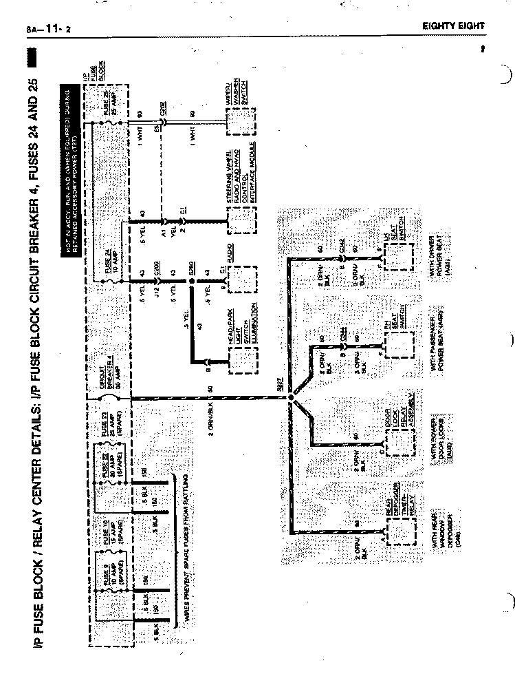
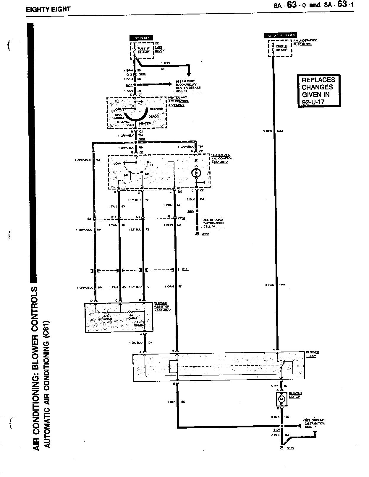
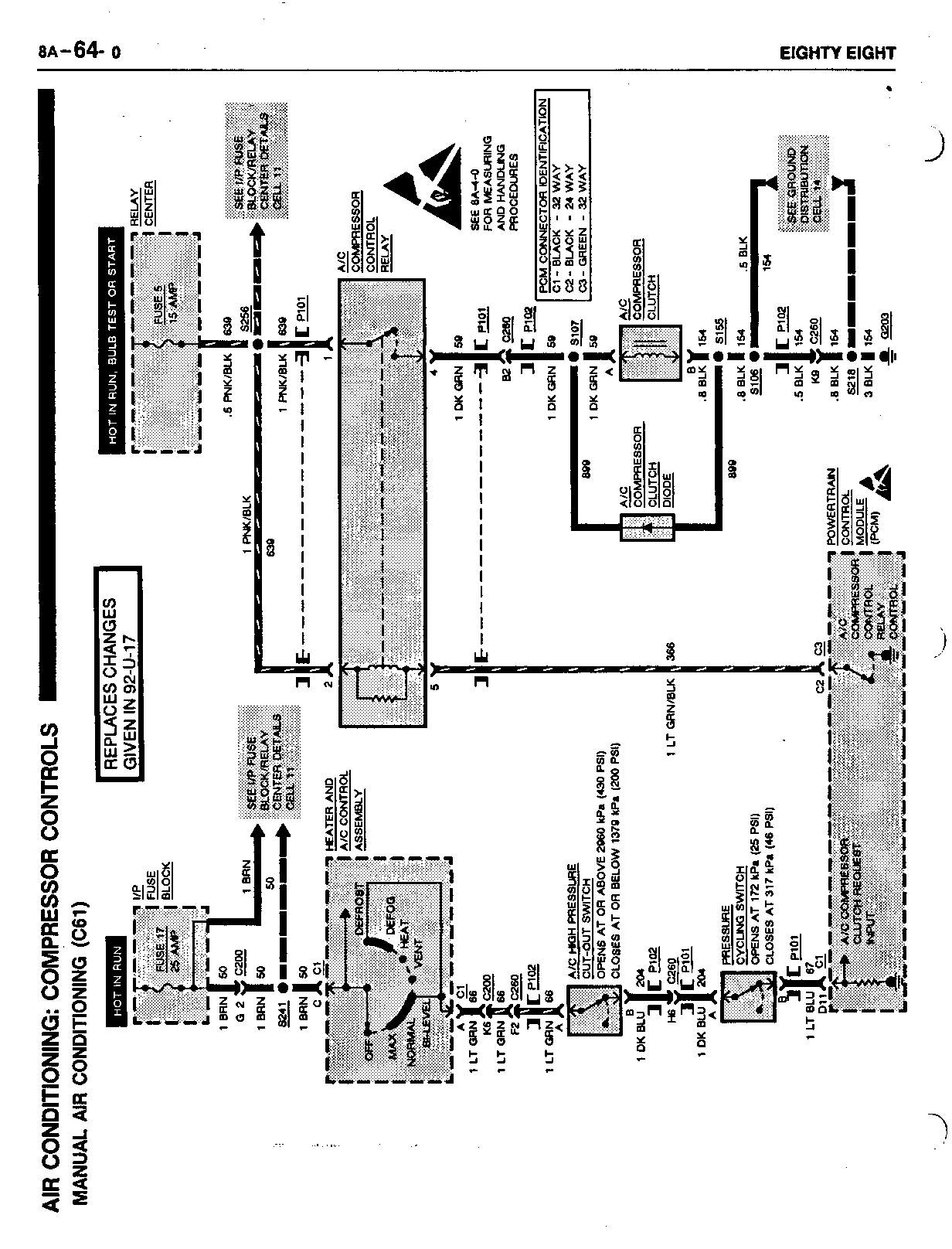
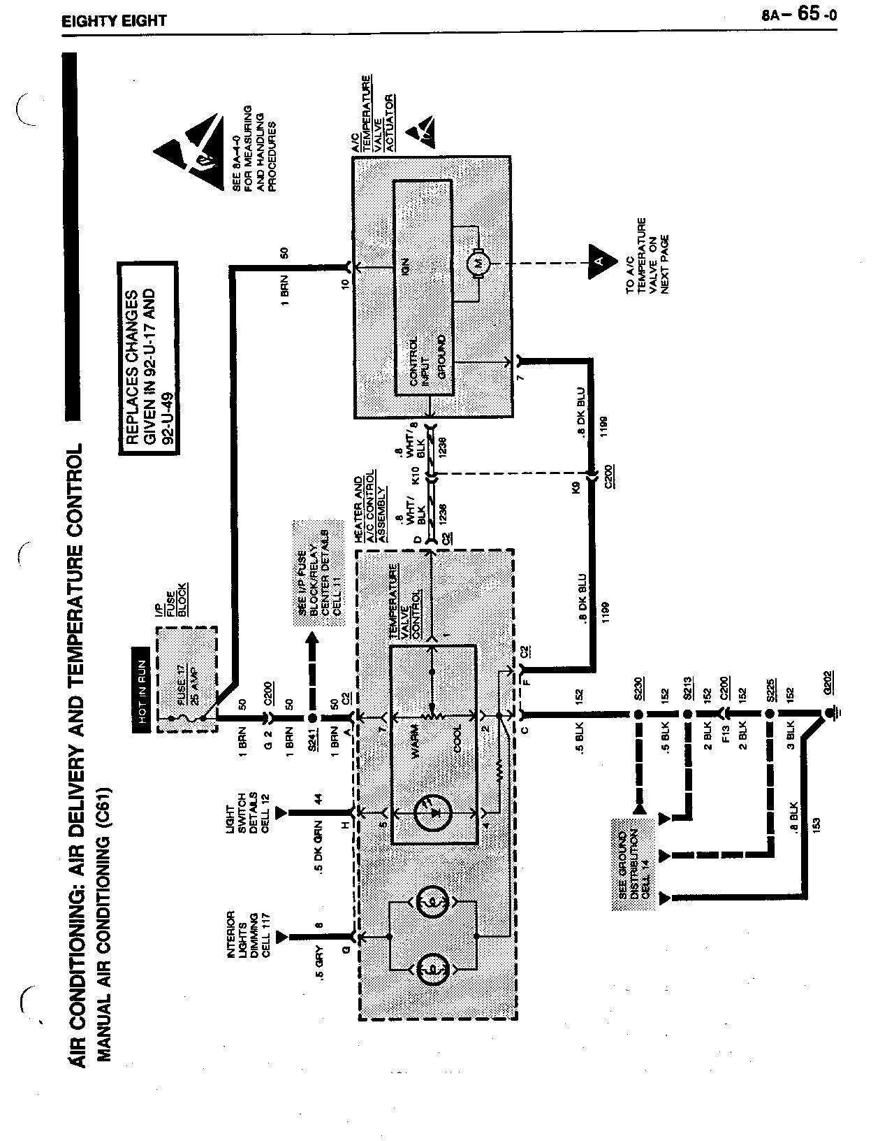
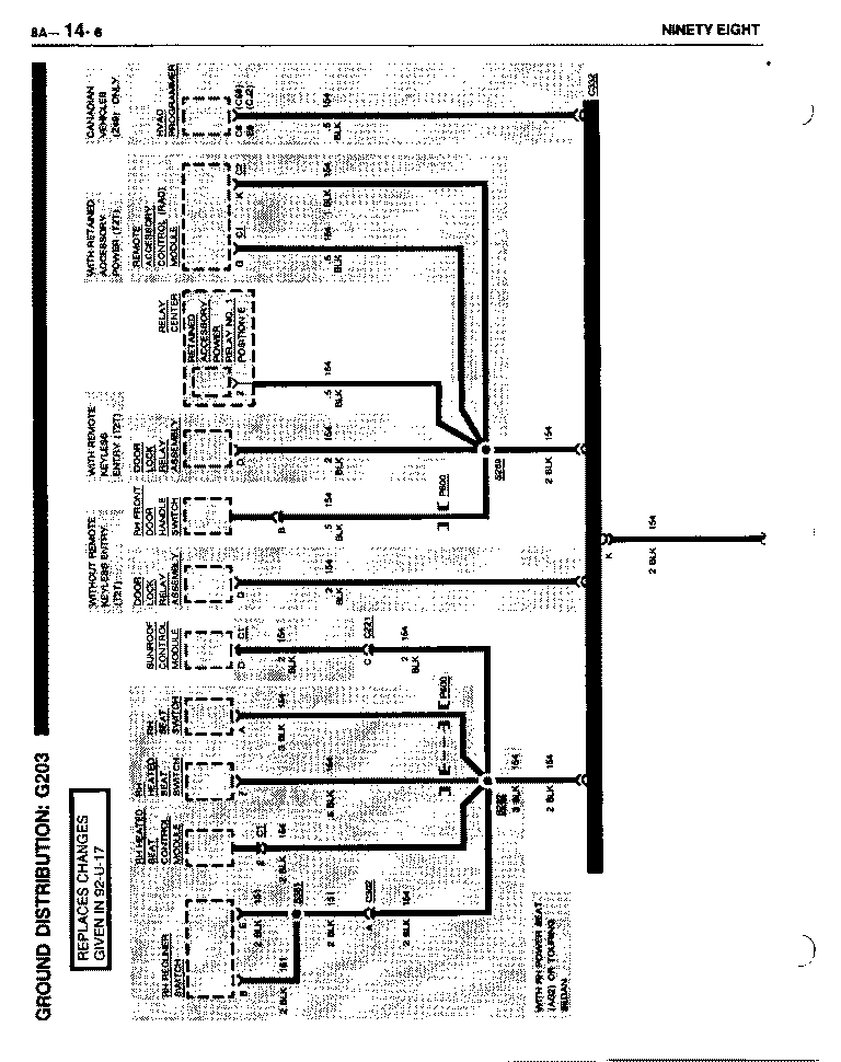
1992 EIGHTY EIGHT Pages(s) Revision ------------------ 8A-11-5 8A-42-0 Change all .5 BRN (50) wires off of splice S241 to 1 BRN (50). 8A-82-2 8A-82-3 ----------------------------------------------------------------------------- 8A-14-2 Change the .5 BLK (155) wire between splice S109 and the Blower Relay to 1 BLK (155). ----------------------------------------------------------------------------- 8A-14-6 Change the .5 BLK (154) wire between the Door Lock Relay Assembly 8A-132-0 and Splice S289 to BLK (154). ----------------------------------------------------------------------------- Change the Defrost-A/C Valve Vacuum Actuator hose connector from 4 to 6. 8A-68-1 Change the Heater-A/C Bi-Level Valve Vacuum Actuator hose connectors from 6 to 4 and from 5 to 3. Change the O/S Air-Recirc. Valve Vacuum Actuator hose connector from 1 to 5. -----------------------------------------------------------------------------
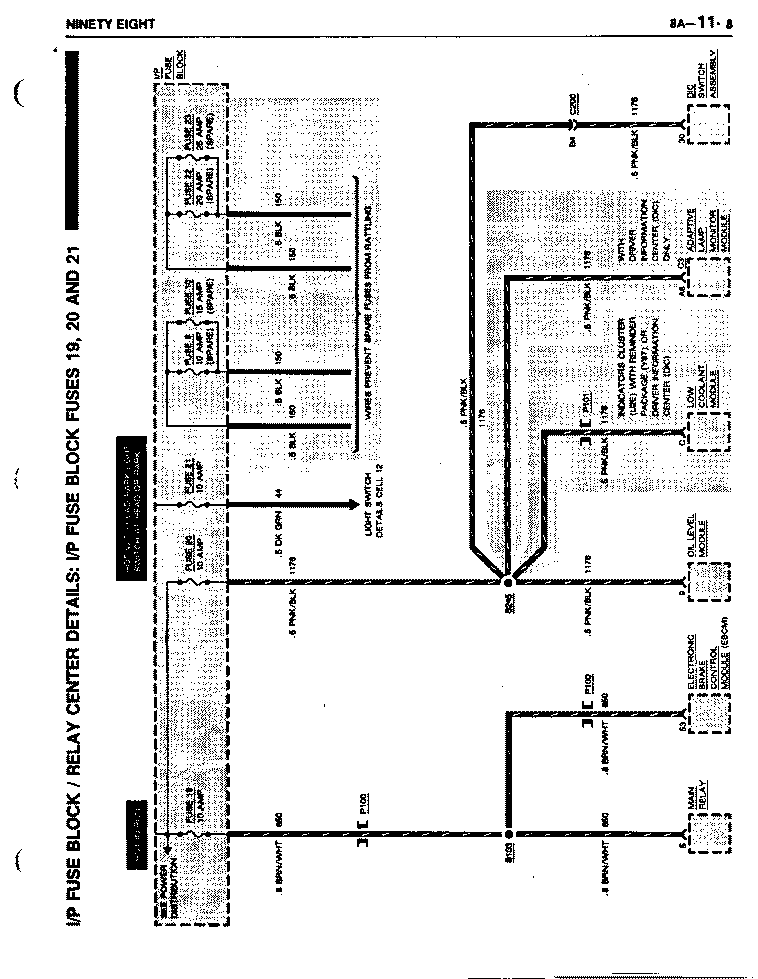
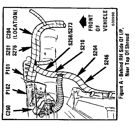
1992 NINETY EIGHT REGENCY Page(s) Revision -------------------- 8A-30-0 Change Splice S267 to S273. ----------------------------------------------------------------------------- 8A-30-1 Remove S267, the Description and Figure number, Add "S273............ Composite harness, behind RH side of I/P ............ 201-14-A." ----------------------------------------------------------------------------- 8A-68-4 Change the Defrost-A/C Valve Vacuum Actuator hose connector from 4 to 6. Change the Heater-A/C Bi-Level Valve Vacuum Actuator hose connectors from 6 to 4 and from 5 to 3. Change the O/S Air-Recirc. Valve Vacuum Actuator hose connector from 1 to 5. ----------------------------------------------------------------------------- 8A-77-0 Change Splice S267 to S273. ----------------------------------------------------------------------------- 8A-77-3 Remove S267, the Description and the Figure number. Add "S273............ Composite harness, behind RH side of IP ............ 201-14-A." ----------------------------------------------------------------------------- 8A-145-0 Change Splice S307 to S308. -----------------------------------------------------------------------------
AIR CONDITIONING: BLOWER CONTROLS
ELECTRONIC AIR CONDITIONING (C68)
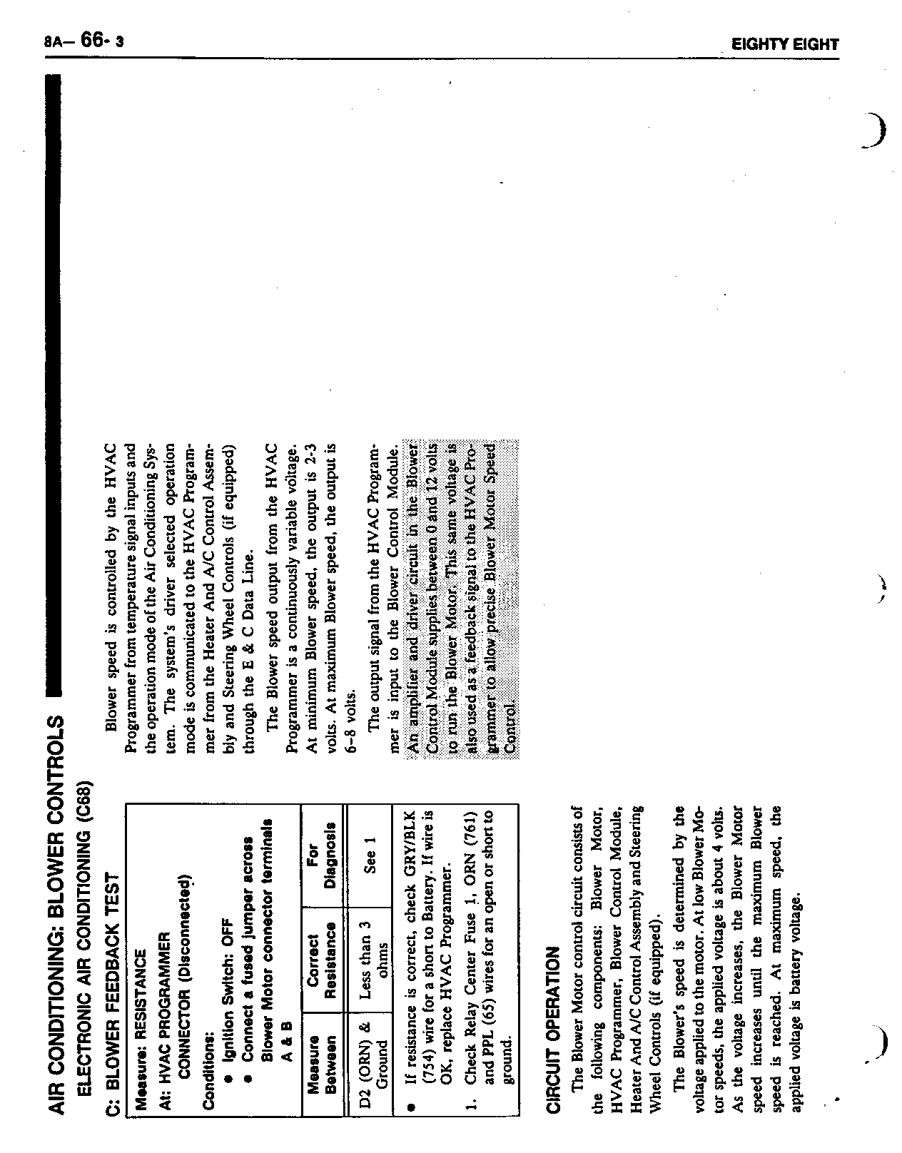
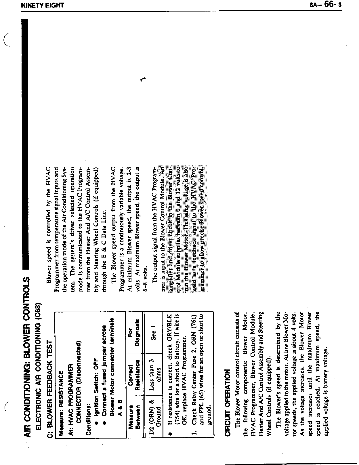
C: BLOWER FEEDBACK TEST
-------------------------------------------------------------------------- Measure: RESISTANCE
At: HVAC PROGRAMMER
CONNECTOR (Disconnected)
Conditions:
o Ignition Switch: OFF o Connect a fused jumper across Blower Motor connector terminals A & B --------------------------------------------------------------------------
Measure Correct For Between Resistance Diagnosis ------- ---------- ---------
D2 (ORN) & Less than 3 See 1 Ground ohms
o If resistance is correct, check GRY/BLK (754) wire for a short to Battery. If wire is OK, replace HVAC Programmer.
1. Check Relay Center Fuse 1, ORN (761) and PPL (65) wires for an open or short to ground. --------------------------------------------------------------------------
CIRCUIT OPERATION
The Blower Motor control circuit consists of the following components: Blower Motor, HVAC Programmer, Blower Control Module, Heater And A/C Control Assembly and Steering Wheel Controls (if equipped).
The Blower's speed is determined by the voltage applied to the motor. At low Blower Motor speeds, the applied voltage is about 4 volts. As the voltage increases, the Blower Motor speed increases until the maximum Blower speed is reached. At maximum speed, the applied voltage is battery voltage.
Blower speed is controlled by the HVAC Programmer from temperature signal inputs and the operation mode of the Air Conditioning System. The system's driver selected operation mode is communicated to the HVAC Programmer from the Heater And A/C Control Assemmbly and Steering Wheel Controls (if equipped) through the E & C Data Line.
The Blower speed output from the HVAC Programmer is a continuously variable voltage. At maximum Blower speed, the output is 2-3 volts. At maximum Blower speed, the output is 6-8 volts.
The output signal from the HVAC Programmer is input to the Blower Control Module. An amplifier and driver circuit in the Blower Control Module supplies between 0 and 12 volts to run the Blower Motor. This same voltage is also used as a feedback signal to the HVAC Programmer to allow precise Blower Motor Speed Control.
General Motors bulletins are intended for use by professional technicians, not a "do-it-yourselfer". They are written to inform those technicians of conditions that may occur on some vehicles, or to provide information that could assist in the proper service of a vehicle. Properly trained technicians have the equipment, tools, safety instructions and know-how to do a job properly and safely. If a condition is described, do not assume that the bulletin applies to your vehicle, or that your vehicle will have that condition. See a General Motors dealer servicing your brand of General Motors vehicle for information on whether your vehicle may benefit from the information.
