SPEEDOMETER/ODOMETER DIAGNOSIS CLUSTER DISASSEMBLY

1985 NINETY-EIGHT
The 1985 Electrical Troubleshooting Manual does not include the speedometer and odometer instrument panel cluster diagnosis and cluster disassembly procedure for 1985 Ninety-Eight models.
Please insert the following information in your 1985 Electrical Troubleshooting Manual.
INSTRUMENT PANEL: STANDARD CLUSTER
INDICATORS
1. If the FUEL GAGE does not read correctly, disconnect the connector from the FUEL TANK UNIT. Connect one clip lead from tester KM J-33431 or equivalent to terminal B (PNK) of the harness connector. Connect the other tester lead to ground.
* With the ignition Switch in "Run" set the tester controls to zero ohms or empty. The FUEL GAGE should indicate E or below.
* Set the tester controls to 90 ohms or full. The FUEL GAGE should indicate F or above.
* If the FUEL GAGE does not respond correctly, install a new FUEL GAGE.
* If the FUEL GAGE responds correctly, check the connector to the sender, the wiring, and the ground connection at G400. If these are good, replace the FUEL TANK UNIT.
Speedometer Does Not Operate
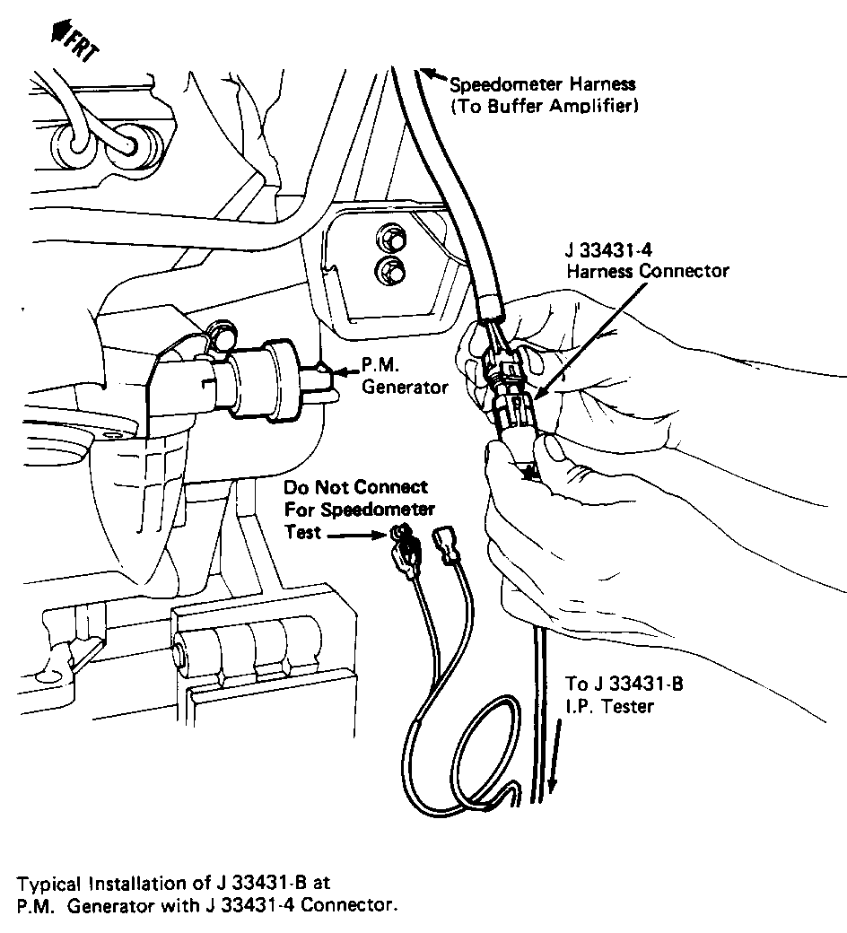
1. If the SPEEDOMETER reads "O" all the time, remove the connector from the VEHICLE SPEED SENSOR. Connect the mating cable from the J-33431 tester to the connector just removed. See Figure 1. Plug in the tester and set switches to "On", "54 mph", and "60 Hz" with the IGNITION SWITCH in "Run".
* The Speedometer should indicate 54 mph +\- 2 mph.
* If the Speedometer indicates correctly, install a new VEHICLE SPEED SENSOR.
2. If the Speedometer does not operate correctly, check the sensor wires to the VEHICLE SPEED SENSOR BUFFER. Remove connector C2 from the buffer and measure the voltage (AC volts) between terminals B (early production) or C (late production) (PPL) and A (YEL) of this connector. It should be approximately 14 volts AC, with the J-33431 tester still connected to the VSS connector and still set to "On", "54 mph", and "60 Hz".
* If the voltage is not 14 volts AC, locate and repair the open or short in the PPL and YEL wires.
* If the voltage is correct, continue to step 3.
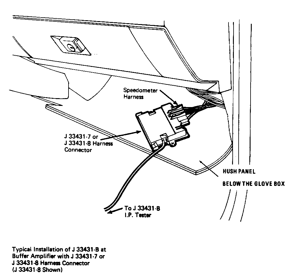
3. To test the VEHICLE SPEED SENSOR BUFFER, remove both connectors from it and plug them into connector J-33431 -8 of the I/P tester. See Figure 2. With the tester set to "On", "54 mph", and "60 Hz" and the IGNITION SWITCH in "Run", the Speedometer should read 54 mph +/- 2 mph.
* If the Speedometer reads correctly, the buffer is bad. Check for Battery voltage between terminal H (PNK/BLK) and terminal A (BLK/WHT) of connector Cl, with the IGNITION SWITCH in "Run". If this is correct, install a new VEHICLE SPEED SENSOR BUFFER.
* If the Speedometer did not indicate correctly, continue to step 4.
4. With the VEHICLE SPEED SENSOR BUFFER reconnected and the IGNITION SWITCH in "Run", backprobe terminal A (BLK/WHT) and C (DK GRN) of connector Cl on the buffer. On the DC volts range, the voltage should be greater than 9 volts.
* If the voltage is not above 9 volts, check the DK GRN 389 wire to the I/P connector C251 for a short or open.
* If the voltage is above 9 volts, go to step 5.
5. Check for Battery voltage supplied to the Speedometer circuit board. Remove the cluster and measure the voltage between terminals N and P of cluster connector C251. Put the IGNITION SWITCH in "Run".
* If Battery voltage is not present, check the PNK/BLK 39 wire and the BLK 150 wire for opens.
* If Battery voltage is present, go to step 6.
6. Inspect the printed circuit for faults between the cluster connector C251 and the speedometer circuit board. Measure the resistance between the following terminals. There should be near zero ohms resistance.
C251 Terminal (Wire Color) and Resistance Speedometer Edgeboard Connector --------------------- ------------
N (PNK&BLK) and LOW A
0 (DK GRN) and LOW B
P (BLK) and LOW C
* If the resistance is not low between all these terminals, replace the flexible printed circuit.
* If the resistances are correct, replace the Speedometer assembly. (See "Cluster Disassembly".)
The Speedometer consists of:
- the gage mechanism.
- the attached circuit board.
* To confirm that the Speedometer assembly is not operating, connect I/P Tester J-33431 to circuit board, using 3-way connector J-33431-9. With the tester plugged in and set to "On", "54 mph", and "60 Hz" the Speedometer should read 54 mph +\- 2 mph.
* If the Speedometer does not indicate properly, the Speedometer is to be sent to an authorized AC-Delco Service Center for repair.
* If the Speedometer operates properly, locate the condition in a vehicle circuit or connector.
Speedometer Is Not Accurate
1. If the Speedometer indicates vehicle speed, but not the correct speed, check for:
* correct tire inflation. * correct tire size. * correct speedometer drive gears in transaxle (see Section 7 of the chassis service manual).
2. If these are correct, perform the electrical diagnosis as in "Speedometer Does Not Operate".
Odometers Do Not Operate
1. If one or both of the Odometers do not turn, and the Speedometer does operate, remove the I/P cluster. See page 8C4-7 in the chassis service manual for cluster removal.
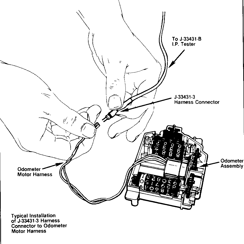
Disassemble the cluster and remove the small odometer connectors from the speedometer circuit board. Connect I/P Tester J-33431-3. See Figure 3. Plug in the I/P Tester and set it to "On", "54 mph", and "60 Hz". With the odometer test switch held down, the Odometer should turn and change the mileage shown about one mile per minute.
* If the Odometer does not turn, replace the stepper motor.
* If the Odometer does turn, check the connector that joins the Odometer to the speedometer circuit board. If the connections are good, the condition is in the speedometer circuit board. The Speedometer is to be sent to an authorized AC-Delco Service Center for repair.
Cluster Disassembly
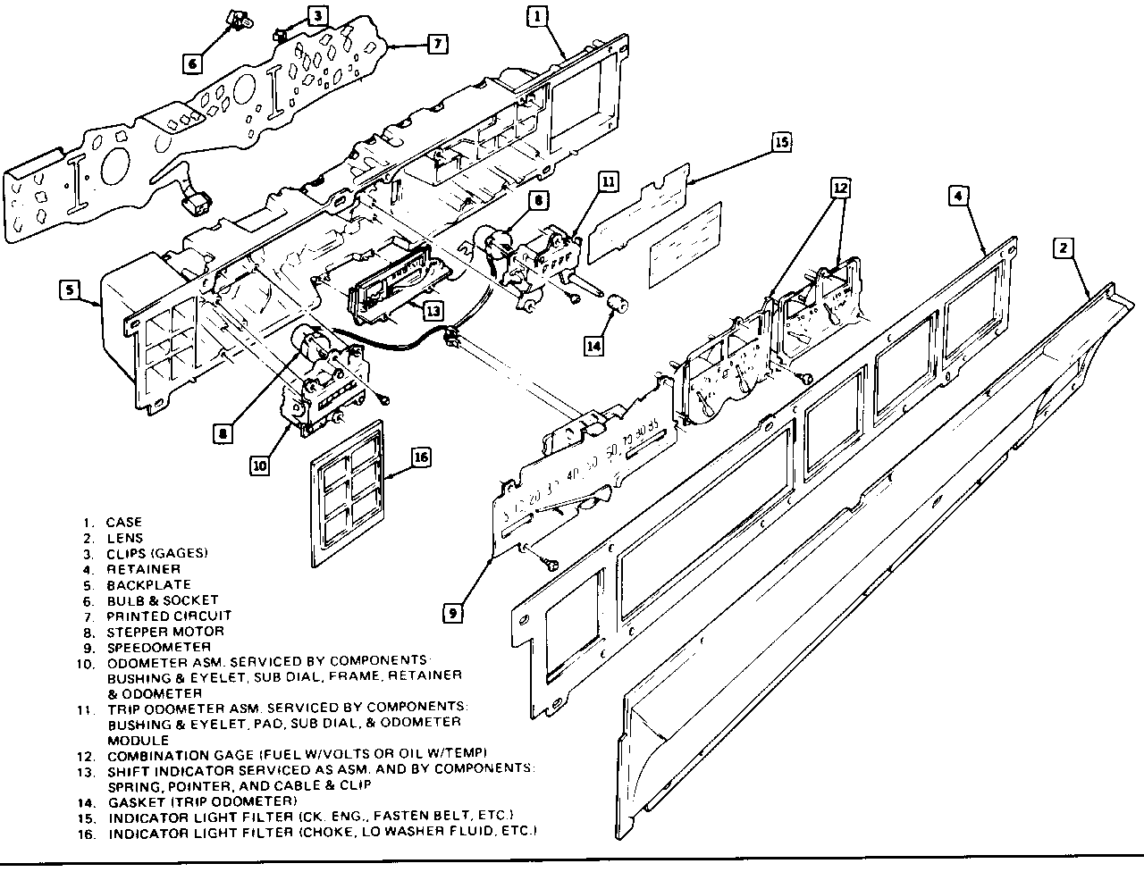
1. Remove the cluster from the car by following the cluster removal procedure on page 8C4-7 of the chassis service manual. See Figure 4.
2. Remove the faceplate, then remove the 3 bulbs at the top of the cluster. If the bulbs are difficult to twist, gently use pliers to twist the bulbs.
3. Take out the PRNDD21 selection indicator piece.
4. Disconnect the 3 pin printed circuit connector beneath the Speedometer.
5. Before the Speedometer, Trip Odometer or Total Odometer can be removed, the two red 2 pin connectors going from the circuit board to the odometers must be disconnected. To do this, first remove the screws holding the Speedometer in place. Then raise the Speedometer about 3 inches and disconnect the Odometer connectors.
6. To remove the Fuel Gage or Total Odometer, take out the screws holding the particular item in place.
7. To remove the Trip Odometer, the Fuel Gage must be removed first.
8. If a condition is found with the Speedometer, the Speedometer assembly must be sent to an authorized AC-Delco Service Center. The Speedometer assembly consists of the Speedometer pointer, air core gage mechanism, and circuit board.
9. If a condition is found with the FUEL, VOLTS, OIL, or TEMP gage, the pointer and air core gage mechanism must be replaced as one unit.
10. If a condition with the Odometer(s) is diagnosed to the circuit board, the stepper motor must be replaced. See Item No. 8 in Figure 4.
11. To remove a stepper motor, first take out the screws holding the odometer module in place and then remove the Odometer.
12. To remove the printed circuit on the back of the cluster, remove all bulbs, then remove the metal clips from the inside of the cluster. The printed circuit is now able to be removed.


General Motors bulletins are intended for use by professional technicians, not a "do-it-yourselfer". They are written to inform those technicians of conditions that may occur on some vehicles, or to provide information that could assist in the proper service of a vehicle. Properly trained technicians have the equipment, tools, safety instructions and know-how to do a job properly and safely. If a condition is described, do not assume that the bulletin applies to your vehicle, or that your vehicle will have that condition. See a General Motors dealer servicing your brand of General Motors vehicle for information on whether your vehicle may benefit from the information.
