Tools Required
J 38400 Brake Spanner
and Remover
- Raise and suitable support the vehicle. Refer to
Lifting and Jacking the Vehicle
in General Information.
- Mark the relationship of the wheel to the wheel studs in the bearing
flange.
- Remove the wheel and tire.
- Mark the relationship of the drum to the wheel studs in the bearing
flange.
- Remove the brake drum. Refer to
Brake Drum Replacement
.

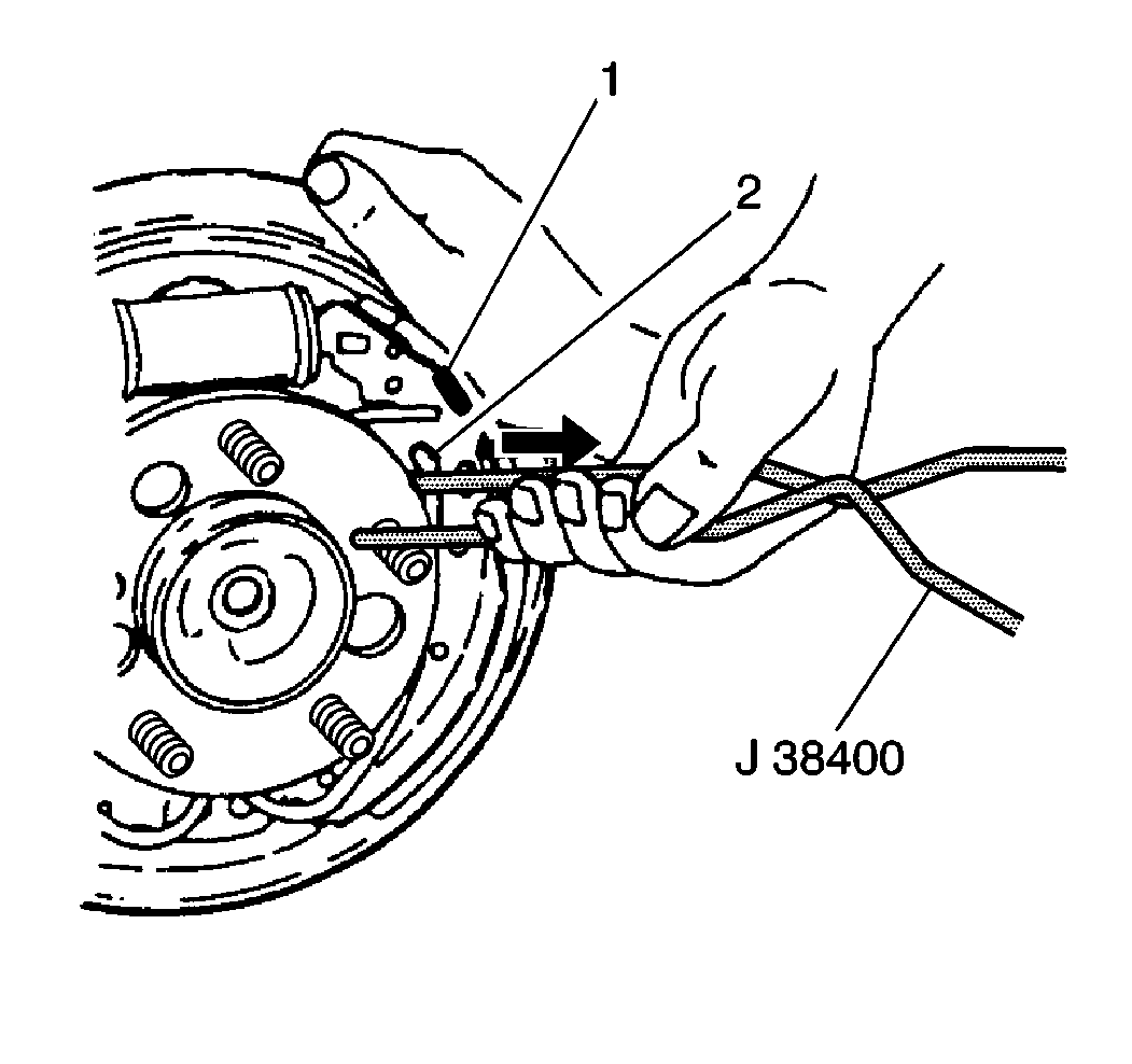
- Remove the actuator spring.
Use the J 38400
in order
to pry the loop end of the spring from the adjuster actuator; then disconnect
the spring from the web of the park brake shoe.

Important: When removing the retractor spring from either shoe and lining, do not
overstretch it. Overstretching reduces the spring's effectiveness.
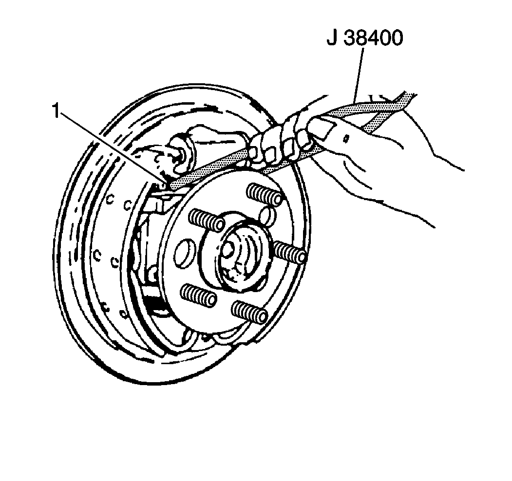
- Lift the end of the retractor spring from the adjuster shoe and lining.
Insert the hook end of J 38400
between the retractor spring and the adjuster shoe web, and pry or
twist to lift the end of the spring out of the shoe web hole.

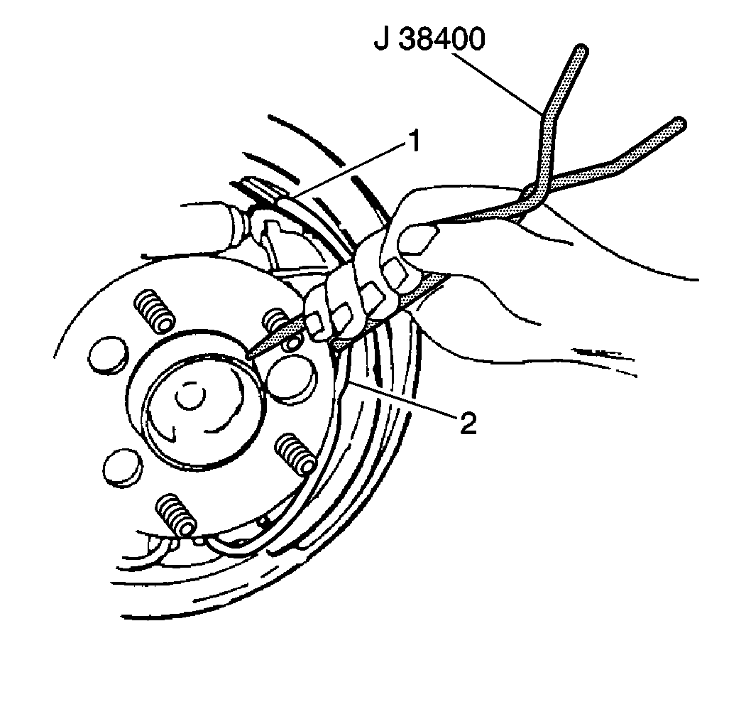
- Pry the end of the retractor
spring toward the axle with the flat edge of J 38400
until the spring snaps down off the shoe web onto the backing
plate.
- Remove the adjuster shoe and lining, adjuster actuator and adjusting
screw assembly.
- Remove the park brake lever from the park brake shoe and lining.
Do not remove the parking brake cable from the park brake lever unless the
lever is to be replaced.

- Lift the end of the retractor
spring from the park brake shoe and lining. Insert the hook end of J 38400
between the retractor spring and park
brake shoe web, and pry or twist to lift the end of the spring out of the
shoe web hole.
- Pry the end of the retractor spring toward the axle with the flat
edge of J 38400
until
the spring snaps down off the shoe web onto the backing plate.
- Remove the park brake shoe and lining. If only the shoes and linings
are being replaced, the retractor spring does not have to be removed. Otherwise,
remove the retractor spring from the anchor plate.
- Clean all parts in clean, denatured alcohol.
Important: Replace any parts which are of doubtful strength or quality due to discoloration
from heat, over stress or wear.
- Check the wheel cylinder for leakage, and cut or damaged boots. Do not
attempt to repair the wheel cylinder; replace the wheel cylinder if it leaks
or is damaged.
Installation Procedure
Important:
| • | Lubricate the following with brake lubricant GM P/N 1052196
or the equivalent: |
| • | Six raised shoe pads on backing plate |
| • | Anchor surfaces on the backing plate that contact the lower ends
of the brake shoes |
| • | When installing retractor spring into either shoe and lining,
do not overstretch it. Overstretching reduces the spring's effectiveness. |
- If the retractor spring was removed, reinstall, hooking the center spring
section under the tab on the anchor.
- Position the park brake shoe and lining on the backing plate.

- Using the J 38400
, pull the end of the retractor spring
up to rest on the web of the brake shoe.

- Using the J 38400
, pull the end of the retractor spring
over until it snaps into the slot in the brake shoe.
- Install the park brake lever to the park brake shoe and lining.
- Connect the parking brake cable to the park brake lever, if it
is disconnected.
- Before reinstalling, disassemble adjusting screw assembly, and
thoroughly clean and lubricate it as follows:
| 7.1. | Clean adjuster screw threads with a wire brush. |
| 7.2. | Wash all components in clean, denatured alcohol. |
| 7.3. | Apply brake lubricant, GM P/N 1052196 or equivalent, to
the adjuster screw threads, the inside diameter of the adjuster socket, and
socket face. A continuous bead of lubricant should be on the end of the
pivot nut and adjuster socket when the threads are fully engaged. |
- Check the adjuster screw threads for smooth rotation over full
length.
- Install the adjusting screw assembly and adjuster shoe lining:
| 9.1. | Engage the pivot nut with the web of the park-brake shoe and lining
and the park brake lever. |
| 9.2. | Position the adjuster shoe and lining such that the shoe web engages
the deep slot in the adjuster socket. |
- Install the retractor spring into the adjuster shoe and lining.
Using J 38400
, pull the
end of the retractor spring up to seat on the web of the brake shoe; then
pull the end of the retractor spring over until it snaps into the slot in
the brake shoe.

- Install the adjuster actuator.
| 11.1. | Lubricate the tab and pivot point on the adjuster actuator with
brake lubricant, GM P/N 1052196 or equivalent. |
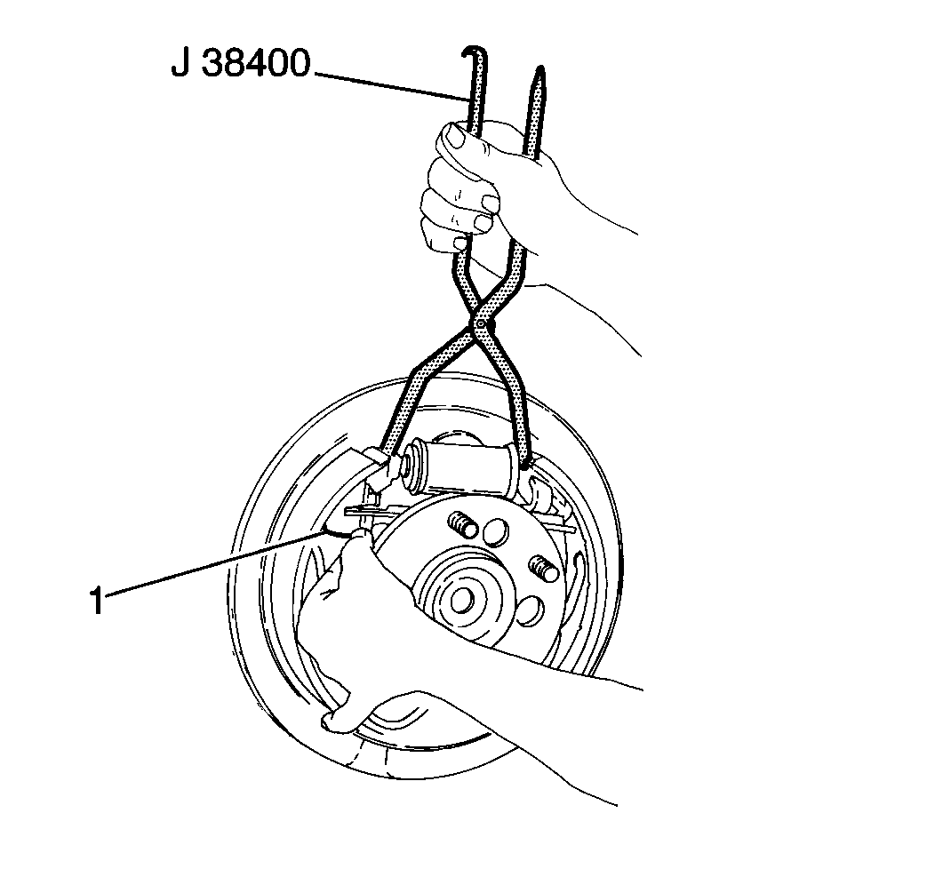
| 11.2. | Using J 38400
,
spread brake shoes while working adjuster actuator into position. |
- Install the actuator spring.
| 12.1. | Engage the U-shaped end of the spring in the hole in the web of
the park brake shoe. |
| 12.2. | Using J 38400
,
stretch the spring and engage the loop end over the tab on the adjuster actuator. |
- Check the following to assure proper position and function of
the adjuster actuator.
| • | Adjuster actuator pivot in the shoe web slot. |
| • | Notch in the adjuster actuator on the stepped edge in adjusting
the screw notch. |
| • | Arm of the adjuster actuator resting freely on the star wheel
teeth of the adjuster screw, not trapped under the teeth in a downward angle. |
| • | Install J 38400
, between the upper ends of the shoe and lining assemblies. Spread
the shoes and the watch for proper rotation of the star wheel. |
Important: Before installing the brake drum and wheel, adjust the following:
- Install brake drum, refer to
Brake Drum Replacement
.
- Install wheel and tire, aligning the marks made at the removal.
Notice: Use the correct fastener in the correct location. Replacement fasteners
must be the correct part number for that application. Fasteners requiring
replacement or fasteners requiring the use of thread locking compound or sealant
are identified in the service procedure. Do not use paints, lubricants, or
corrosion inhibitors on fasteners or fastener joint surfaces unless specified.
These coatings affect fastener torque and joint clamping force and may damage
the fastener. Use the correct tightening sequence and specifications when
installing fasteners in order to avoid damage to parts and systems.
- Tighten the wheel
nuts.
Tighten
Tight the wheel nuts to 140 N·m (100 lb ft).
- Lower the vehicle.


