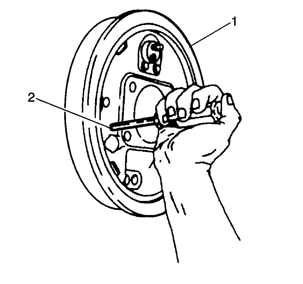
Removal Procedure
Important: While installing a new brake drum, do not refinish the braking surface,
as it is already at the correct level of finish.
- Raise and suitably support the vehicle. Refer to Vehicle Lifting and
Jacking in General Information.
- Mark the relationship of the wheel to the wheel studs in the bearing
flange.
- Remove the wheel and the tire.
- Mark the relationship of the drum to the wheel studs in the bearing
flange.

Notice: Do not pry against the splash shield which surrounds the backing plate
in an attempt to free the drum. This will bend the splash shield.
- Remove the brake drum. If the drum is difficult to remove, use the following
procedure:
| 5.1. | Make sure the parking brake is released. |
| 5.2. | Back off the parking brake cable adjustment. |
| 5.3. | Use a hammer and a small metal punch to bend in the backing plate
knockout slug to provide access to the park brake lever. |
| 5.4. | Insert the metal punch or a screwdriver through the hole and press
in to push the park brake lever off its stop. This lets the shoe and linings
retract slightly. |
| 5.5. | Apply a small amount of penetrating oil around the drum pilot
hole. |
Important: After the drum has been removed from the vehicle, be sure to remove
the knockout slug, using pliers or vise grips. Then insert a rubber access
hole plug (service part) into the hole to prevent dirt or contamination from
entering the drum brake assembly.
- Before installing brake drum and wheel, adjust the following items:
Installation Procedure

- Install the brake drum, aligning
the marks made at the removal.
- Install the wheel and the tire, aligning the marks made at the
removal.
- Lower the vehicle.
Notice: Use the correct fastener in the correct location. Replacement fasteners
must be the correct part number for that application. Fasteners requiring
replacement or fasteners requiring the use of thread locking compound or sealant
are identified in the service procedure. Do not use paints, lubricants, or
corrosion inhibitors on fasteners or fastener joint surfaces unless specified.
These coatings affect fastener torque and joint clamping force and may damage
the fastener. Use the correct tightening sequence and specifications when
installing fasteners in order to avoid damage to parts and systems.
- Tighten the wheel
nuts.
Tighten
Tighten the wheel nuts to 140 N·m (100 lb ft).


