Radio Antenna Replacement US6
Removal Procedure
Tools Required
J 38536-A Antenna
Bezel Nut Socket
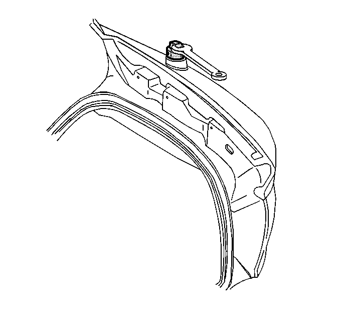
- Install tape onto the contacting surfaces of the tool to be used in loosening the radio fixed antenna mast.
- Using the taped tool, loosen the fixed antenna mast.
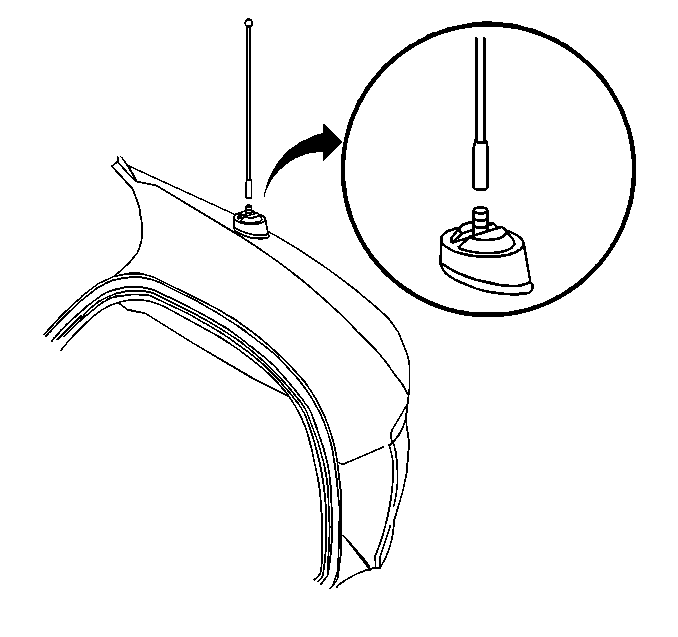
- Remove the antenna mast from the fixed antenna.
- Open the rear compartment lid.
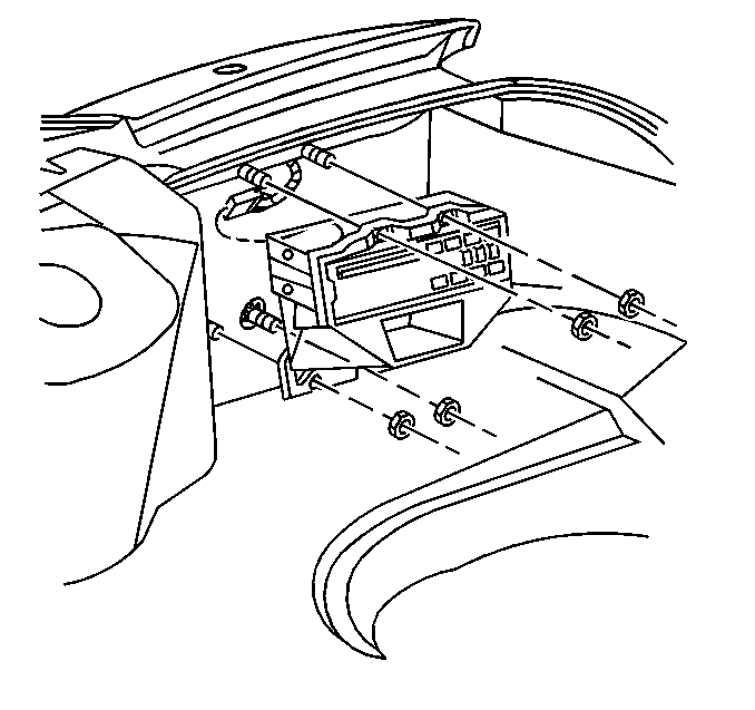
- Remove the nuts retaining the remote compact disc (CD) player mounting bracket, if equipped, then reposition the mounting bracket.
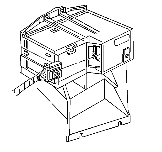
- Disconnect the electrical/audio connector from the remote CD player, if equipped.
- Remove the remote CD player with mounting bracket, if equipped.
- Reposition the RH side of the rear compartment trim panel in order to access the fixed antenna. Refer to Rear Compartment Trim Panel Replacement in Body Rear End.
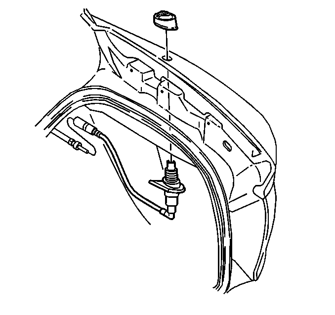
- Using the J 38536-A , loosen and remove the antenna bezel retaining nut.
- Disconnect the antenna extension cable from the fixed antenna.
- Remove the antenna bezel.
- Remove the fixed antenna.
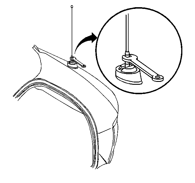
Important: Be sure to use tape on the contacting surfaces of the tool used in order to protect the paint on the antenna mast.
Installation Procedure
- Install the fixed antenna into position.
- Install the antenna bezel.
- Loosely install the antenna bezel retaining nut.
- Connect the antenna extension cable to the fixed antenna.
- Using the J 38536-A , tighten the antenna bezel retaining nut.
- Install the RH side of the rear compartment trim panel into position. Refer to Rear Compartment Trim Panel Replacement in Body Rear End.
- Connect the electrical/audio connector to the remote CD player, if equipped.
- Position the remote CD player mounting bracket, if equipped, onto the mounting studs in the rear compartment.
- Install the remote CD player mounting bracket retaining nuts, if equipped.
- Close the rear compartment lid.
- Install the fixed antenna mast to the fixed antenna.
- Using the tool taped previously, tighten the antenna mast.


Notice: Use the correct fastener in the correct location. Replacement fasteners must be the correct part number for that application. Fasteners requiring replacement or fasteners requiring the use of thread locking compound or sealant are identified in the service procedure. Do not use paints, lubricants, or corrosion inhibitors on fasteners or fastener joint surfaces unless specified. These coatings affect fastener torque and joint clamping force and may damage the fastener. Use the correct tightening sequence and specifications when installing fasteners in order to avoid damage to parts and systems.
Tighten
Tighten the radio fixed antenna bezel retaining nut to 10 N·m
(89 lb in).


Tighten
Tighten the remote CD player mounting bracket retaining nuts to 7 N·m
(62 lb in).


Tighten
Tighten the radio fixed antenna mast to 5 N·m (44 lb in).
Radio Antenna Replacement Rear Window Antenna (U77)
Grid Line/Terminal Repair
If a portion of the rear window antenna grid lines are broken or if the antenna terminal is disconnected from the antenna grid, it may be repaired. These repair procedures are the same as the rear window defogger grid line and terminal repair procedures. Refer to Grid Line Repair , or Bus Bar/Antenna Terminal Repair in Stationary Windows.
