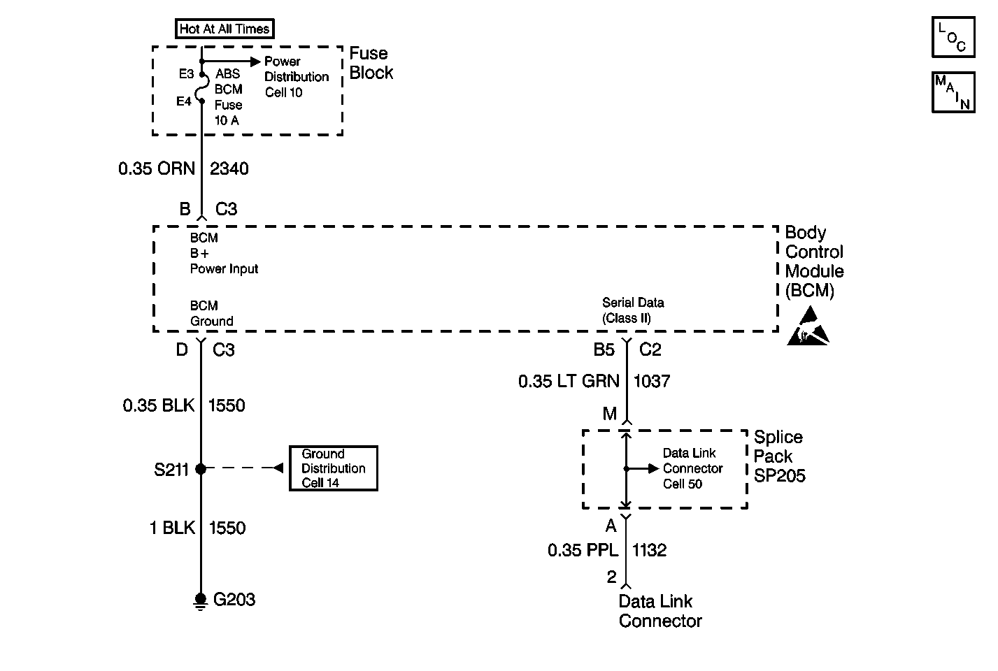
System Description
The Body Control Module (BCM) diagnostic system check is an organized approach to identify problems associated with the BCM. The BCM diagnostic system check must be the starting point for any BCM-related complaint. The BCM diagnostic system check will direct you to the next logical step in diagnosing the complaint. The BCM is a very reliable component and it is not likely the cause of the malfunction. Most BCM system malfunctions are linked to faulty wiring, connectors, and occasionally to other vehicle components. Understanding the BCM and using the diagnostic tables correctly will reduce diagnostic time and prevent unnecessary parts replacement.
Diagnostic Aids
| • | Use a J 35616-A when probing or checking electrical connector terminals. The J 35616-A prevents terminal damage, plus checks for proper terminal contact tension. |
| • | If the BCM malfunction is intermittent, refer to Intermittents and Poor Connections for more information. |
| • | Exit all scan tool tests before cycling the ignition switch to off, unless indicated by the scan tool. Follow the scan tool user's manual. Failure to follow these instructions may set DTCs, cause vehicle system malfunctions, set false DTCs, or cause scan tool malfunctions. |
| • | DTC P1626 will set in the Powertrain Control Module (PCM) when the ignition switch is on with the Body Control Module (BCM) disconnected. When BCM diagnostics and repairs are completed, refer to Powertrain Control Module Diagnosis for additional information on PCM related DTCs. |
Test Description
The number(s) below refer to the step number(s) on the diagnostic table.
-
Determines whether the Class II serial data link has a circuit malfunction or the BCM is not communicating with the scan tool.
-
Checks for a short to ground in circuit 2340.
-
Checks for an open in circuit 2340.
-
Checks for an open in circuit 1550.
-
Checks for an open in circuit 1037.
-
Checks for a faulty BCM.
-
Checks for BCM current DTCs stored in memory.
-
Checks for BCM history DTCs stored in memory.
-
Checks for an intermittent BCM system malfunction.
Step | Action | Value(s) | Yes | No | ||||||
|---|---|---|---|---|---|---|---|---|---|---|
1 |
Does the scan tool establish communication with the BCM? | -- | ||||||||
Using scan tool, attempt to establish communications with these vehicle systems:
Does the scan tool communicate with the vehicle systems listed above? | -- | |||||||||
3 | Check the ABS-BCM fuse. Is the ABS-BCM fuse open? | -- | ||||||||
Is the ABS-BCM fuse open again ? | -- | |||||||||
Is the test light on? | -- | |||||||||
Using a test light, connect between the BCM harness connector C3 terminals B and D. Is the test light on? | -- | |||||||||
Is the resistance within the specified range? | Less than 2ohms | |||||||||
Does the scan tool establish communication with the BCM? | -- | |||||||||
9 | The scan tool is unable to establish communication with vehicle systems because of a Class II serial data link circuit malfunction. Refer to Data Link Communications System Check in Wiring Systems for the diagnosis and repair of the Class II serial data link. Is the action complete? | -- | -- | |||||||
10 | Repair short to ground in circuit 2340. Is the repair complete? | -- | -- | |||||||
11 | Repair poor connection or open in circuit 2340. Is the repair complete? | -- | -- | |||||||
12 | Repair poor connection or open in circuit 1550. Is the repair complete? | -- | -- | |||||||
13 | Repair poor connection or open in circuit 1037. Is the repair complete? | -- | -- | |||||||
14 |
Is the repair complete? | -- | -- | |||||||
Using scan tool, check for BCM current DTCs. Refer to Diagnostic Trouble Code (DTC) Displaying for more information. Are any BCM current DTCs present? | -- | |||||||||
Are any BCM current DTCs present? | -- | |||||||||
17 |
Is the action complete? | -- | -- | |||||||
18 | For each BCM current DTC, perform corresponding diagnostic table. Refer to Diagnostic Trouble Code (DTC) List/Type for more information. When dealing with several current DTCs, start with DTC with the lowest number, then proceed to the next DTC with a higher number until all current DTCs are diagnosed and repaired. Is the action complete? | -- | -- | |||||||
Using scan tool, check for DTC history DTC(s). Refer to Diagnostic Trouble Code (DTC) Displaying for more information. Are any BCM current DTCs present? | -- | -- | ||||||||
20 |
Is the action complete? | -- | -- |
