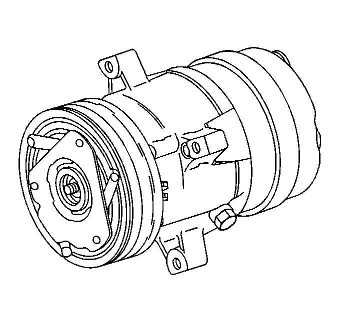
Vehicles using the V5
Compressor may require different installation procedures because of differences
in the following components:
Basic overhaul procedures for compressors used on different vehicles
are similar.
When servicing the compressor, prevent dirt and foreign material from
entering the following areas:
| • | The compressor components |
Ensure that the following items are clean at all times in order to complete
proper service of the compressor:
Clean the compressor connections and the outside of the compressor prior
to any on-vehicle repairs or before removal of the compressor.
Use the following cleaning agents in order to clean any components that
will be reassembled:
Dry the components with air. Use only lint-free cloths in order to wipe
the components.
The operations described in the unit repair procedures for the V5 Compressor
are based on a bench overhaul with the compressor removed from the car, except
as noted.
Notice: Up to 120 ml (4 oz) of PAG Lubricant can collect in the
crankcase. Therefore, it is important when replacing a compressor that the
PAG Lubricant in the old compressor crankcase be drained through the drain
plug and measured. Discard after recording the amount.
Following the removal of a compressor from the car for service, drain
the remaining amount of the PAG lubricant from the compressor. Measure and
record the amount of the PAG lubricant drained from the compressor. Discard
the old PAG lubricant. Add an equal amount of new PAG lubricant to the compressor.
All replacement compressors are shipped with 270 ml (9 oz)
of PAG lubricant in the crankcase. Drain and retain this lubricant. Replace
the lubricant in the same amount as previously recorded from the old compressor.
Replace the lubricant only with GM approved PAG lubricant.
V5 Compressor -- Theory of Operation
The V5 is a variable displacement compressor. The V5 can match the automotive
air conditioning demand under all conditions without cycling. The basic compressor
mechanism is a variable angle wobble-plate with five axially-oriented cylinders.
The control center of the compressor displacement is a bellows-actuated
control valve. The control center is located in the rear head of the compressor
that senses the compressor suction pressure. The crankcase-suction pressure
differential controls the wobble-plate angle and the compressor displacement.
When the A/C capacity demand is high, the suction pressure is above the
control point. At this point the control valve maintains a bleed from the
crankcase to the suction. With no crankcase-suction pressure differential,
the compressor has maximum displacement. When the A/C capacity demand is
lower and the suction pressure reaches the control point, the valve bleeds
discharge gas into the crankcase. The valve closes off a passage from the
crankcase to the suction plenum. A force balance on the five pistons controls
the angle of the wobble-plate. A slight elevation of the crankcase-suction
pressure differential creates a total force on the pistons. This force causes
a movement about the wobble-plate pivot pin that reduces the plate angle.
The compressor has a unique lubrication system. The crankcase-suction
bleed is routed through the rotating wobble-plate in order to lubricate the
wobble-plate bearing. The rotation acts as an oil separator. The rotation
removes some of the oil from the crankcase-suction bleed. The rotation also
reroutes the oil to the crankcase in order to lubricate the compressor
mechanism.
Minor Compressor Repair Procedures
Keep the following items clean at all times in order to complete proper
service of the compressor:
Remove only the components that preliminary diagnosis determines are
in need of service.
Major Compressor Repair Procedures

Discharge the refrigerant
from the system when replacing the following components:
| • | The shaft seal assembly |
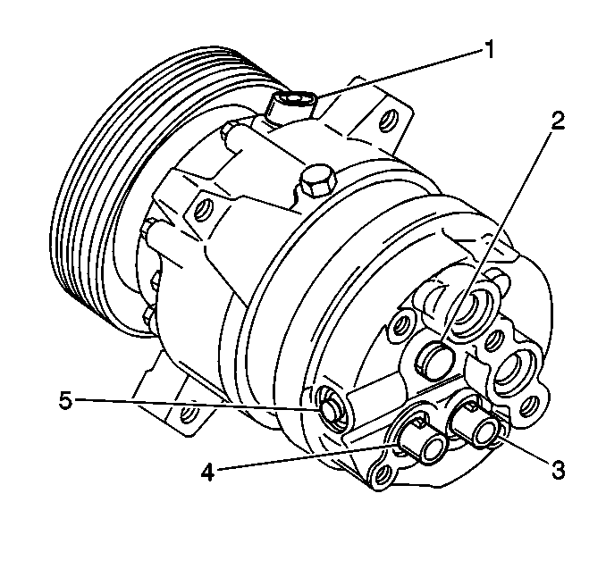
| • | The pressure relief valve (2) |
| • | The rear head mounted pressure switches (3, 4) |
Discharge the system even when the compressor remains on the vehicle
during the above procedures.
Discharge the refrigerant from the system before any disassembly of
the compressor except for clutch repair procedures.
Notice: Any attempt to use makeshift or inadequate service tools
or equipment may result in damage and/or improper compressor operation.
Prepare a clean workbench covered with a sheet of clean paper. Prepare
a location with clean trays for all the components being removed and replaced.
Use the proper service tools. Ensure that
the tools are clean.
All the components necessary for servicing the internal compressor are
protected by a preservative process. All of the above components are packaged
in a manner which eliminates the necessity
of the following actions:
| • | Cleaning the components |
| • | Flushing the components |
Use the components in internal assembly just as the components are removed
from the service package. Do not open the seals and the protective packaging
until just prior to the installation.
Drain the oil from the compressor when servicing or replacing one of
the following components:
| • | The compressor rear head |
| • | The compressor front head |
| • | The cylinder and shaft assembly |
Measure the amount of oil drained. Record the measurement. Replace the
drained oil with new oil.
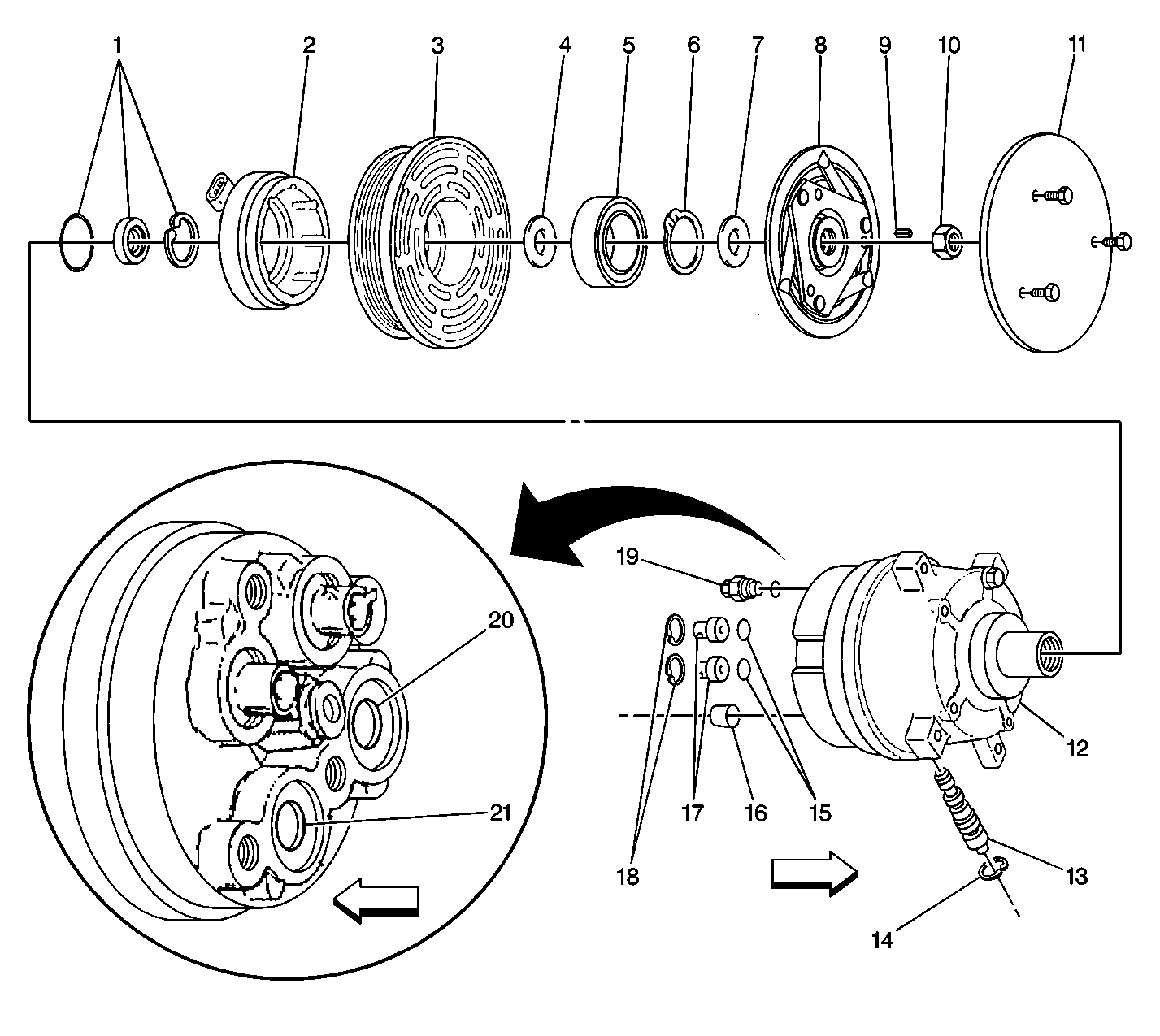
V5 A/C Compressor Components


