Removal Procedure
- Remove the air cleaner and duct assembly. Air Cleaner Assembly Replacement in Engine Controls.
- Recover the refrigerant. Refer to Refrigerant Recovery and Recharging .
- Remove the brake modulator/master cylinder. Refer to Brake Modulator/Master Cylinder Assembly Replacement in Antilock Brake System.
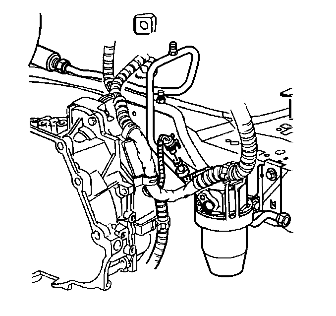
- Disconnect the electrical connector to the A/C refrigerant pressure sensor.
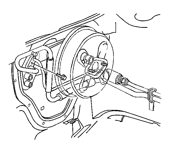
- Remove the liquid line/suction line bracket.
- Remove the liquid line fitting at the orifice.
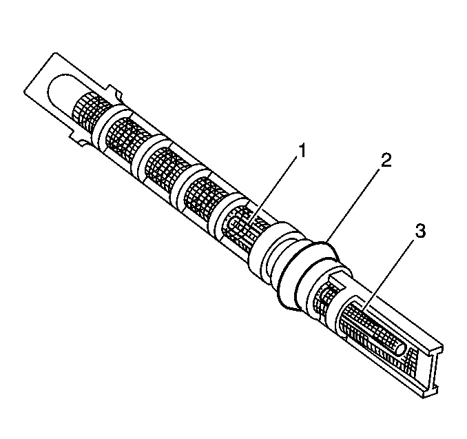
- Remove the expansion (orifice) tube.
- Remove the impacted residues.
- Using a heat gun (hair dryer, epoxy dryer or the equivalent), apply heat approximately ¼ inch from the dimples on the inlet pipe. Do not overheat the pipe.
- While applying heat, perform the following steps:
- Add 30 ml (1 oz) of Polyalkylene Glycol (PAG) Synthetic Refrigerant Oil to the system.
- Lubricate the new expansion (orifice) tube and O-ring seal with mineral base 525 viscosity refrigerant oil and insert into the inlet pipe.
- Install tube with the smaller screen (3) first.
- Remove the O-rings seals (2).


Important: If the expansion (orifice) tube is restricted or plugged, perform the following procedure:
| 10.1. | Use needle-nose pliers in order to grip the orifice tube. |
| 10.2. | Use a turning motion along with a push-pull motion in order to loosen the impacted orifice tube. |
| 10.3. | Remove the orifice tube. |
Installation Procedure
- Install the new O-ring seals (2).
- Install the liquid line fitting at the orifice.
- Install the liquid line/suction line bracket.
- Connect the electrical connector to the A/C refrigerant pressure sensor.
- Install the brake modulator/master cylinder. Refer to Brake Modulator/Master Cylinder Assembly Replacement in Antilock Brake System.
- Evacuate and recharge the system. Refer to Refrigerant Recovery and Recharging .
- Inspect the A/C system for leaks. Refer to Leak Testing .
- Install the air cleaner and duct assembly. Refer to Air Cleaner Assembly Replacement in Engine Controls.

Important: Coated the new O-ring seals (2) with mineral base 525 viscosity refrigerant oil.
Install the new expansion (orifice) tube with the shorter screen (3) end in first.

Notice: Use the correct fastener in the correct location. Replacement fasteners must be the correct part number for that application. Fasteners requiring replacement or fasteners requiring the use of thread locking compound or sealant are identified in the service procedure. Do not use paints, lubricants, or corrosion inhibitors on fasteners or fastener joint surfaces unless specified. These coatings affect fastener torque and joint clamping force and may damage the fastener. Use the correct tightening sequence and specifications when installing fasteners in order to avoid damage to parts and systems.
Tighten
Tighten the liquid line fitting to 27 N·m (20 lb ft).


