Purpose
Varying octane levels in today's gasoline may cause detonation (spark knocking) in some engines. Detonation is caused by an uncontrolled explosion (burn) in the combustion chamber. This uncontrolled explosion could produce a flame front opposite to the normal flame front produced by the spark plug. The rattling sound, normally associated with detonation, is the result of two or more opposing flame fronts colliding within the combustion chamber. Though light detonation is sometimes considered normal, heavy detonation could result in engine damage. To control spark knock, a knock sensor (KS) system is used. If engine detonation occurs, the KS system retards the spark timing. The KS system allows the engine to use maximum spark advance for optimal driveability and fuel economy.
Operation
The knock sensors, located in the engine block near the cylinders, detect abnormal vibration (spark knocking) in the engine. The knock sensors produce an AC signal under all engine operating conditions. Integrated diagnostic circuitry allows the PCM to detect engine detonation and diagnose the sensors and related wiring. If engine detonation occurs, the PCM retards Ignition Control (IC) spark timing relative to the amplitude and frequency of the KS signal being received.
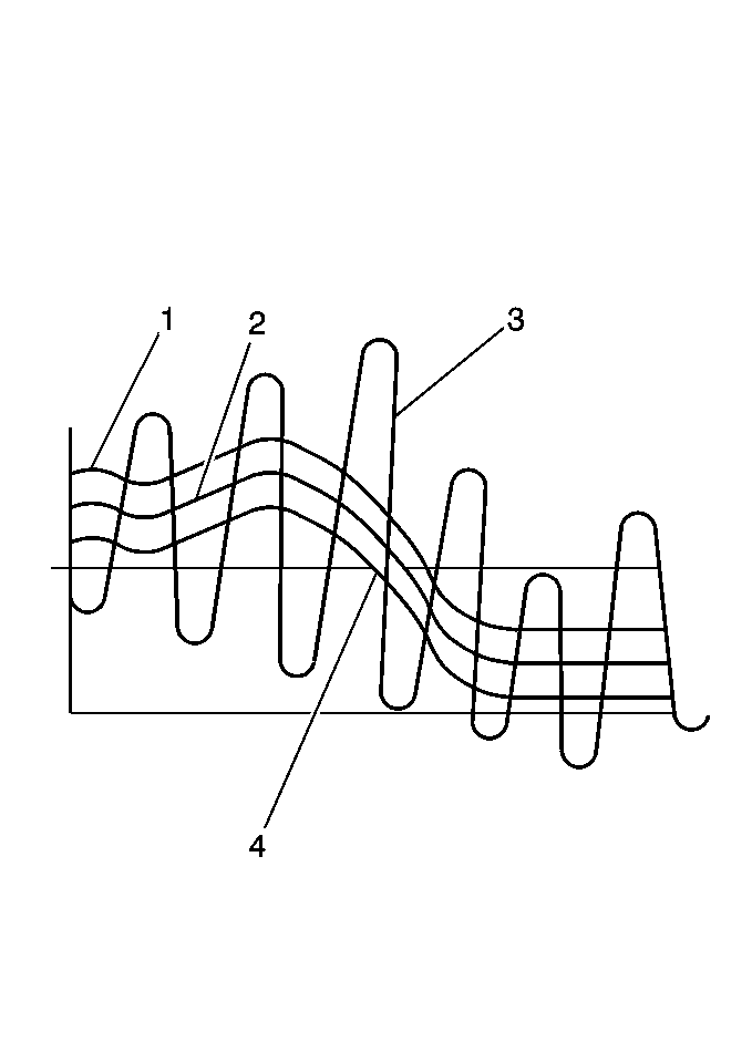
The PCM contains integrated knock sensor (KS) diagnostic circuitry. During operation, the PCM calculates an average voltage of each knock sensor's signal and performs instantaneous signal voltage readings. The PCM uses the instantaneous signal voltage readings to determine the state of the knock sensor circuitry. If the knock sensor system is operating normally, the PCM monitors instantaneous signal voltage readings varying outside a voltage range above and below the calculated average voltage (refer to the normal knock sensor figure).
If PCM detects a signal voltage within the calculated average voltage range, DTC P0327 or P0332 will set (refer to the abnormal knock sensor figure).

