Purpose
The electronic ignition system controls fuel combustion by providing
a spark to ignite the compressed air/fuel mixture at the correct time. To
provide optimum engine performance, fuel economy, and control of exhaust
emissions, the PCM controls the spark advance of the ignition system. Electronic
ignition has the following advantages over a mechanical distributor system:
| • | Remote mounting capability. |
| • | No mechanical load on the engine. |
| • | More coil cool down time between firing events. |
| • | Elimination of mechanical timing adjustments. |
| • | Increased available ignition coil saturation time. |
Operation
The electronic ignition system does not use the conventional distributor
and coil. The ignition system consists of 3 ignition coils, an ignition control
module (ICM), a dual Hall-effect crankshaft position (CKP) sensor, an engine
crankshaft balancer with interrupter rings attached to the rear, the related
connecting wires, and the Ignition Control (IC) and fuel metering portion
of the PCM.
Conventional ignition coils have one end of the secondary winding connected
to the engine ground. However, in this ignition system, neither end of the
secondary winding is grounded. Instead, each end of a coil's secondary winding
is attached to each spark plug of the 2 cylinders designated to share the
coil (1/4, 2/5, 3/6). These 2 cylinders are referred to as companion cylinders,
i.e., on top dead center at the same time. When the coil discharges, both
plugs fire at the same time to complete the series circuit. The cylinder on
compression is said to be the event cylinder and the one on exhaust is the
waste cylinder. The cylinder on the compression stroke requires most of the
secondary coil's available voltage to fire the spark plug. The remaining
energy is used as required by the cylinder on the exhaust stroke. The same
process is repeated when the cylinders reverse roles. This type of ignition
is called a waste spark ignition system.
On a conventional ignition system the spark plugs fire with the same
polarity (forward). If the polarity of the conventional ignition system was
reversed, the spark plugs would fire backwards. Since the required voltage
to fire the spark plugs backwards is higher, and coil design limited the
secondary coil's available voltage, a weak spark or misfire could occur.
However, in the waste spark ignition system, the polarity of the ignition
coil primary and secondary windings is fixed. One spark plug always fires
with normal polarity and its companion plug fires with reverse polarity.
The voltage required by each spark plug is determined by the polarity and
the cylinder pressure. The cylinder on the compression stroke requires more
voltage to fire the spark plug than the cylinder on the exhaust stroke. Because
of improved coil design, and increased primary current flow and saturation
time, the ignition coils produce a higher secondary voltage - greater than
40 kilovolts (40,000 volts) at any engine RPM. The higher available
voltage provides more than enough energy required by the event cylinder,
the additional spark plug gap, and the reverse polarity of the waste cylinder.
It is possible for one spark plug to fire even though a plug wire from
the same coil may be disconnected from its companion plug. The disconnected
plug wire acts as one plate of a capacitor, with the engine being the other
plate. These 2 capacitor plates are charged as a spark jumps across the
gap of the connected spark plug. The plates are then discharged as the secondary
energy is dissipated in an oscillating current across the gap of the spark
plug that is still connected. Secondary voltage requirements are very high
with an open spark plug or spark plug wire. The ignition coil has enough
reserve energy to fire the plug that is still connected at idle, but the
coil may not fire the spark plug under high engine load. A more noticeable
misfire may be evident under load as both spark plugs may then be misfiring.
System Components

Crankshaft Position Sensor and Crankshaft Balancer Interrupter Rings
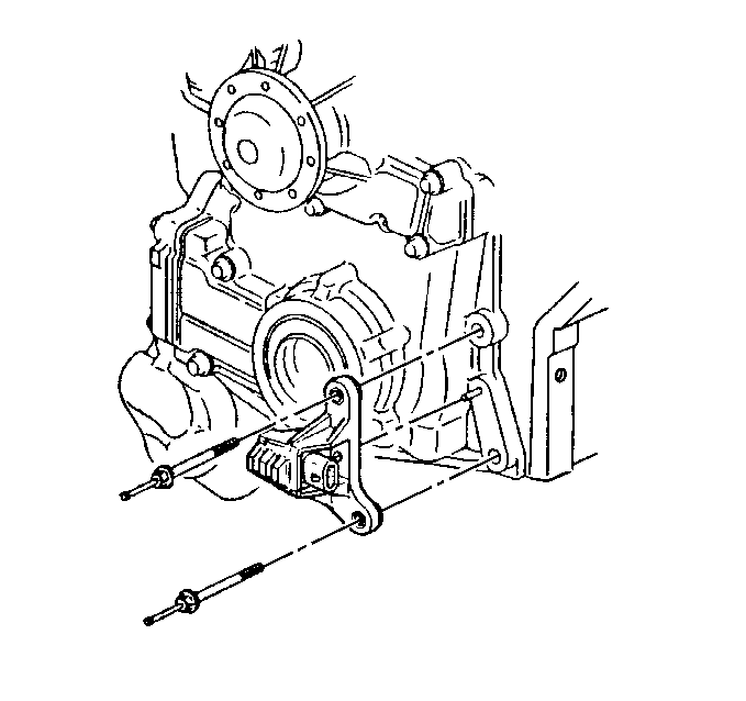
The dual crankshaft position (CKP) sensor is secured in an aluminum
mounting bracket and bolted to the front left side of the engine timing chain
cover, partially behind the crankshaft balancer. A 4-wire harness connector
plugs into the sensor, connecting the sensor to the ignition control module
(ICM) . The dual crankshaft position sensor contains 2 Hall-effect switches
with one shared magnet mounted between them. The magnet and each Hall-effect
switch are separated by an air gap. A Hall-effect switch reacts like a solid
state switch, grounding a low current signal voltage when a magnetic field
is present. When the magnetic field is shielded from the switch by a piece
of steel placed in the air gap between the magnet and the switch, the signal
voltage is not grounded. If the piece of steel (called an interrupter) is
repeatedly moved in and out of the air gap, the signal voltage appears to
oscillate on and off repeatedly. In the case of the electronic ignition system,
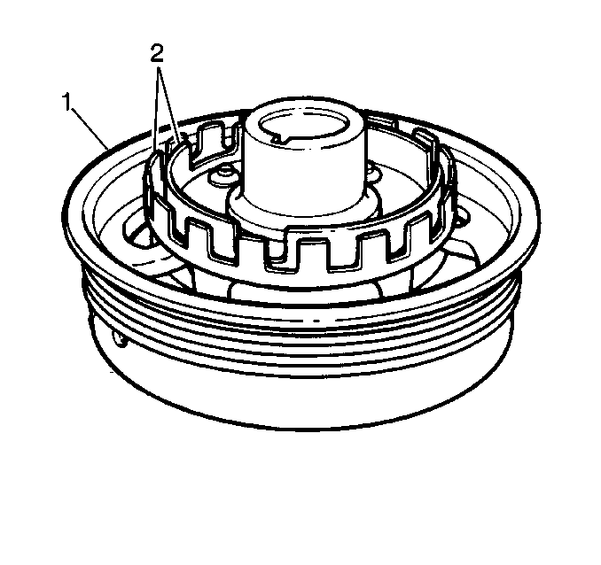
the piece of steel is 2 concentric interrupter rings mounted to the rear
of the crankshaft balancer.


