Removal Procedure
Tools Required
J 35917 Tie Rod Puller/Ball Joint Remover
- Raise and support the vehicle. Refer to Lifting and Jacking the Vehicle in General Information.
- Remove the left tire and wheel assembly. Refer to Wheel Removal in Tires and Wheels.
- Remove the right stabilizer shaft link bolt.
- Remove the left stabilizer shaft link bolt.
- Disconnect Power Steering Pressure Switch
- Remove the nut from the tie rod end at the steering knuckle. Refer to Rack and Pinion Outer Tie Rod End Replacement .
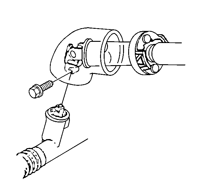
- Disconnect the intermediate shaft lower bolt. Refer to Intermediate Steering Shaft Replacement Steering Wheel and Column-Tilt.
- Remove the pipe retaining clip from the steering gear.
- Remove all pipes, hoses and clips from the steering gear.
- Use a utility stand in order to support the frame rear.
- Remove the frame rear bolts and lower the frame. Refer to Frame Replacement in Frame and Underbody.
- Remove the power steering gear mounting bolts and nuts.
- Remove the power steering gear through the left wheel opening.

Notice: Use only the recommended tools for separating the tie rod ends from the knuckle/strut. Failure to use the recommended tools may cause damage to the tie rod and seal.

Notice: Set steering shaft so the block tooth on the upper steering shaft is at the 12 o'clock position, the wheels on the vehicle are straight ahead and set the ignition switch to the LOCK position. Failure to follow these procedures could result in damage to the coil.
Notice: Do not lower the rear of the frame too far as damage to the engine components nearest to the cowl may result.
Installation Procedure
- Install the power steering gear through the left wheel opening.
- Install the power steering gear mounting bolts.
- Install the power steering gear mounting nuts.
- Install the inlet pipe.
- Install the outlet line fittings and seals to the steering gear.
- Install the pipe retaining clip to the steering gear.
- Raise the frame rear.
- Install the new frame rear bolts. Refer to Frame Replacement in Frame and Underbody.
- Remove the utility stand from the frame.
- Connect the intermediate shaft lower bolt. Refer to Intermediate Steering Shaft Replacement Steering Wheel and Column-Tilt.
- Install the tie rod ends to the steering knuckles. Refer to Rack and Pinion Outer Tie Rod End Replacement .
- Install the left stabilizer shaft link bolt.
- Install the right stabilizer shaft link bolt.
- Install the left tire and wheel assembly. Refer to Wheel Installation in Tires and Wheels.
- Lower the vehicle.
- Fill the system with power steering fluid. Refer to Checking and Adding Power Steering Fluid .
- Bleed the air from the system. Refer to Power Steering System Bleeding .
- Inspect the system for leaks. Refer to Power Steering Gear and Pump Leaks .
- Adjust the toe as needed. Refer to Front Toe Adjustment in Wheel Alignment.
Notice: Use the correct fastener in the correct location. Replacement fasteners must be the correct part number for that application. Fasteners requiring replacement or fasteners requiring the use of thread locking compound or sealant are identified in the service procedure. Do not use paints, lubricants, or corrosion inhibitors on fasteners or fastener joint surfaces unless specified. These coatings affect fastener torque and joint clamping force and may damage the fastener. Use the correct tightening sequence and specifications when installing fasteners in order to avoid damage to parts and systems.
Tighten
Tighten the power steering gear mounting nuts to 80 N·m
(59 lb ft).
Inspect the O-rings. Replace the O-rings as needed.
Tighten
Tighten the fittings to 27 N·m (20 lb ft).

Important: When installing the intermediate shaft ensure that the shaft is seated prior to the bolt installation. If the bolt is inserted into the coupling before shaft installation, the two mating shafts may disengage.

Tighten
Tighten the bolt to 47 N·m (35 lb ft).
Tighten
Tighten the bolt to 47 N·m (35 lb ft).
