SERVICE MAN.UPDATE SEC.8A ELECT.DIAGNOSTIC REVISION

SUBJECT: SERVICE MANUAL UPDATE - SECTION 8A - ELECTRICAL DIAGNOSIS (DIAGNOSTIC REVISIONS)
VEHICLES AFFECTED: 1990 "W" MODELS
This bulletin provides late Production and revised information to supplement Section 8A.
The Update Change Summary follows the Service Manual Index. The Summaries show the minor wiring changes since Publication of the final edition of the 1990 Service Manual.
All changes are labeled with a late Production or revised not to help identify the type of revision.
Multi-Use Index allows the user to reference the Section 8A Supplement or 1990 Service Manual.
Please update your Service Manual accordingly.
Service Manual Page/Revision Page and Category --------------- -------------- Air Conditioning Air Delivery and Conditioning Controls ...................... 65-0 ............65-0 3 Blower Controls................. 63-0 ............63-2 3 Compressor Controls ............ 64-0 ............64-0, 64-3 3 System Check ................... 62-0 Anti-lock Brake System............ 44-0 ........... 44-0 3, 44-14 3, 44-16 3, 44-18 3, 44-84 3, 44-86 3, 44-90 3, 44-96 3 Audio Alarm System ............... 76-0 Automatic Safety Belts ...........146-0 ...........146-1 3 Brake Warning System ............ 41-0 ............41-0 3 Charging System ................. 30-0 ............30-0 3 Cigar Lighter ....................114-0 Component Center Automatic Seatbelts Fuse........ 11-5 ............11-5 3 Foglight Relay Fuse ............ 11-8 ............11-8 3 Headlight Circuit Breaker....... 11-8 ............11-8 3 Power Windows Circuit Breaker... 11-8 ............11-8 3 Connectors ...................... 202-0 ..........202-15 2 Coolant Fan ..................... 31-0 .... 31-0-A 1, 31-1-A 1, 31-3-A 1, 31-4-A 1, 31-5-A 1, 31-6-A 1, 31-7-A 1, 31-8-A 1 Cruise Control.................... 34-0 ............34-0 3 Data Line ........................ 51-0 ............51-1 3 Defogger (Rear) .................. 61-0 ............61-0-A 1 Electronic Instrument Cluster: Base 80-0 ............80-23 Electronic Instrument Cluster: UB3 81-0 ............81-0 3, 81-2 3 Engine Multiport Fuel Injection: V6 VIN T...................... 20-0 ............20-0 3, 20-2 3, 20-4 3 Fuse Block Details................ 11-0 ............ 11-0 2, 11-1 3, 11-5 3, 11-6 3, 11-8 3, 11-11 3, 11-13 3 Gages Base Cluster Fuel ......................... 80-2 .............80-2 3 Gages (UB3) Cluster Coolant Temperature........... 81-0 .............81-0 3 Fuel ......................... 81-0 .............81-0 3 Odometer .................... 81-0 .............81-0 3 Oil Pressure .................81-0 .............81-0 3 Speedometer ................. 81-0 .............81-0 3 Tachometer .................. 81-0 .............81-0 3 Voltmeter .................... 81-0 .............81-0 3 Ground Distribution ...............14-0 Harness Routing Views ............203-0 Headlights With T61 ...................... 104-0 ...........104-0 3, 104-1 3, 104-2 3, 104-3 3, 104-4 3, 104-10 3 Without T61 ................... 100-0 ......... 100-0 3, 100-1 3 100-2 3 Heater .......................... 65-0 Horns ........................... 40-0 ............ 40-1 3 Indicators Base Cluster Antilock Brakes ...............80-0 Brake Warning .................80-0 Charge ....................... 80-0 Coolant Temperature............80-0 Cruise........................ 80-0 Fasten Belts...................80-1 Hi Beam ...................... 80-1 Low Coolant .................. 80-0 LH Turn ...................... 80-1 Oil Pressure ..................80-0 RH Turn ...................... 80-1 Service Engine Soon........... 80-0 Gages (UB3) Cluster Antilock Brakes................81-2 .............81-2 3 Brake Warning................. 81-2 .............81-2 3 Hi Beam .......................81-2 ............81-2 3
Service Manual Page/Revision Page and Category -------------- ------------- LH Turn ...................... 81-2..............81-2 3 Low Coolant .................. 81-2..............81-2 3 RH Turn....................... 81-2..............81-2 3 Safety Belts.................. 81-2..............81-2 3 Service Engine Soon........... 81-2..............81-2 3 Key Cylinder Light............... 115-0 Light Switch Details.............. 12-0..............12-0 3, 12-1 3 12-2 3 Lights (Exterior) Back up ....................... 112-0 Fog With T61 .................... 104-2............ 104-2 3, 104-3 3, 104-4 3, 104-10 3 Without T61 ................. 100-0 ........... 100-0 3, 100-1 3 Front Marker................. 110-1 Hazard....................... 110-0 Headlights With T61................... 104-0 ............104-0 3, 104-1 3, 104-2 3, 104-3 3, 104-4 3, 104-10 3 Without T61 ............... 100-0 ............100-0 3, 100-1 3, 100-2 3 High Level Stop...............110-0 License ......................110-5 Park ........................ 110-1 Rear Marker ..................110-5 Rear Turn ....................110-5 Stop ........................ 110-3 Tail......................... 110-3 Tum.......................... 110-1 Lights (Interior) Ashtray...................... 114-0 Courtesy..................... 114-1 Dimming ..................... 117-0 Dome..........................114-1 I/P Compartment.............. 114-0 Luggage Compartment ..........114-0 Mirror....................... 114-1 Reading ..................... 114-1 Rear Courtesy................ 114-1 Underhood ................... 114-0 Vanity Mirror................ 114-0 LS Electrical Center ECM Fuse...................... 11-10 Luggage Compartment Release...... 134-0 Power Antenna ................... 151-0 Power Distribution................ 10-0 ............ 10-0 3, 10-1 3, 10-2 3 Power Door Locks ................ 130-0 .............130-0 3 Power Mirrors ................... 141-0 Power Seats ..................... 140-0 Power Windows .................. 120-0 Radio/Clock ..................... 150-0 .............150-0 3, 150-2 3 RS Electrical Center............. 11-11 ............ 11-11 3 Starter .......................... 30-0 ..............30-0 3 Steering Wheel Controls: UK3 ......89-0 Vehicle Speed Sensor.............. 33-0 Warnings and Alarms ............. 76-0 ..............76-0 3 Wiper/Washer With Pulse...................... 91-0 Without Pulse .................. 90-0
KEY: 1 - Late Production 2 - Revised 3 - Refer to Update Change Summary on following page
Update Change Summary
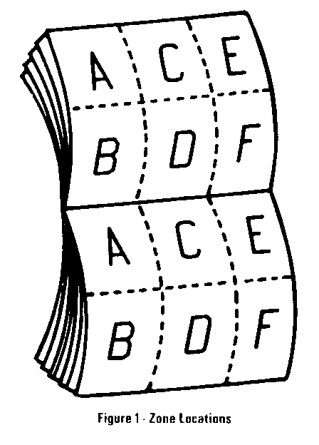
The Update Change Summary describes the revisions, the category of revision, the cell and page number, and the zone where the revision can be located on the schematic. The schematic is separated into six zones so that information can be easily and consistently located within Section 8A. Figure 1 below shows the zone locations. It is recommended that you transfer the minor change information into the Update Change Summary to your 1990 Service Manual.
Multi-Use Index
The Multi-Use Index contains all information regarding the 1990 Service Manual plus all the information included in the Section 8A Supplement. This allows the user to enter the Section 8A Supplement or 1990 Service Manual by using just one index. Pagenumbers for the 1990 Service Manual are under the heading SERVICE MANUAL, PAGE. Pages included in the Section 8A Supplement are highlighted in boldface type and page numbers are under the heading PAGE/REVISION AND CATEGORY. The number located to the upper right of the page number under the PAGE/REVISION AND CATEGORY column identifies the category of the revision. Note the Key located in the Index which defines what the individual numbers represent.
Late Production and Revised Notes
The Late Production and Revised notes are used throughout the Section 8A Supplement to identify the type of revisions that occurred during the model year. LATE PRODUCTION indicates that cars were built as shown in the Late Production revision as well as shown in the schematic in the respective 1990 Service Manual. Page numbers for Late Production schematics are noted in the Index and are in boldface type. Late Production schematics are identified by an "A " following the page number (example 42-0-A). The "A " indicates that there are two schematics that represent how the car was built. Using this example, 42-0-A shows the Late Production version and 42-0, in the 1990 Service Manual, shows another earlier version of how the car was built.
REVISED indicates that revisions occurred; however, the cars were built only in the way the Revised schematic represents. Revised schematics are noted in the Index with bold type, using the same page number used in the 1990 Service Manual. Note, a Revised schematic supersedes the respective page in the 1990 Service Manual.
For details on how to use this cell, refer to Contents page.
Page Zone Revision Category Revision ------- ---- -------------------- -------------------------------- 8A-10-0 B Late Production Change the RED/WHT wires to RED Revised Change LUGGAGE COMPARTMENT RELEASE Fuse to TRUNK REL Fuse Change the Primary Coolant Fan Relay to the Primary Cooling Fan Relay Change pin 4 of the Primary Cooling Fan Relay to pin 3
F Late Production Change the amperage of the 16 BELT Fuse from 5 Amp to 10 Amp
8A-10-1 D Revised Change 13 ALT Fuse to 13 IGN Fuse Change 10 CLST Fuse to 10 CLUST Fuse
8A-10-2 D Revised Change 11 INJ/PFI Fuse to 11 INJ V6 Fuse Change 12 INJ/PFI Fuse to 12 INJ V6 Fuse Change 11 INDIC Fuse 5 Amp to 5 INDIC Fuse 10 Amp Insert a YEL pigtail between pin G and the Transaxle Position Switch
8A-11-0 C Revised Change 11 INDIC Fuse 5 Amp to 5 INDIC Fuse 10 Amp
8A-11-1 B Late Production Change the 1 ORN (740) wire between pins B1 and B5 of the Horn Relay to.8 ORN (740)
8A-11-5 C Late Production Change the amperage of the 16 BELT Fuse from 5 Amp to 10 Amp
8A-11-6 E Late Production Change 5 INDIC Fuse 10 Amp to 11 PANEL Fuse 5 Amp
8A-11-8 A Late Production Change the.8 DK GRN (860) wire to 1 DK GRN (860)
8A-11-11 C Revised Change pin 3 of the A/C Compressor Control Relay to pin 1
D Revised Change the Primary Coolant Fan Relay to the Primary Cooling Fan Relay Change pin 3 of the Primary Coolant Fan Relay to pin 2 Change the Secondary Coolant Fan Relay to the Secondary Cooling Fan Relay Change pin 3 of the Secondary Coolant Fan Relay to pin 2
For details on how to use this cell, refer to Contents page.
Page Zone Revision Category Revision -------- ----- ----------------- -------------------------------- 8A-11-13 A Revised Change 18 LUGGAGE COMPARTMENT RELEASE Fuse to 18 TRUNK REL Fuse
B Revised Insert a PNK/BLK pigtail between pin D and the Transaxle Position Switch
D Revised Change 13 ALT Fuse to 13 IGN Fuse
8A-12-0 A Late Production Change the .8 DK GRN (860) wire to 1 DK GRN (860)
C Late Production Change 5 INDIC Fuse 10 Amp to 11 PANEL Fuse 5 Amp
D Late Production Change the .5 YEL (317) wire to .8 YEL (317) Change the .5 BRN (230) wires to.5 BRN/WHT (230)
8A-12-1 A, C Late Production Change reference from To INDIC Fuse On Page 12-0 to To PANEL Fuse On Page 12-0
B, D, F Revised Change.8 BRN/WHT (9) wires to .8 BRN (9)
C Late Production Change.5 PNK wires to.5 WHT wires
E Late Production Change the .5 BRN (9) wire between splice S119 and pin D2 of Connector C150 to .8 BRN (9)
8A-12-2 A Late Production Change the.8 DK GRN (860) wire to 1 DK GRN (860)
C Late Production Change 5 INDIC Fuse 10 Amp to 11 PANEL Fuse 5 Amp
D Late Production Change the .5 YEL (317) wire to .8 YEL (317) Change the.5 BRN (230) wires to.5 BRN/WHT (230)
For details on how to use this cell, refer to Contents page.
Page Zone Revision Category Revision ------- ---- ----------------- ------------------------------------- 8A-20-0 A Revised Change 11 INDIC Fuse 5 Amp to 5 INDIC Fuse 10 Amp
c Revised Change ECM Connector Identification from A-YEL-22 Way to A-ORN- 22 Way Change ECM Connector Identification from C-GRN-22 Way to C- GRY-22 Way
D Revised Change pin C of connector C1 to pin A
8A-20-2 A Revised Change 13 ALT Fuse to 13 IGN Fuse
B Revised Change ECM Connector Identification from A-YEL-22 Way to A-ORN- 22 Way
Change ECM Connector Identification from C-GRN-22 Way to C- GRY-22 Way
c Revised Change 11 INJ/PFI Fuse to 11 INJ V6 Fuse
E Revised Change 12 INJ/PFI Fuse to 12 INJ V6 Fuse
8A-20-4 B Revised Change ECM Connector Identification from A-YEL-22 Way to A-ORN- 22 Way Change ECM Connector Identification from C-GRN-22 Way to C- GRY-22 Way
E Revised Change 11 INDIC Fuse 5 Amp to 5 INDIC Fuse 10 Amp
8A-30-0 A Revised Insert YEL pigtail between pin G and Transaxle Position Switch
B Revised Insert PPL pigtail between pin E and Transaxle Position Switch
E Revised Change 11 INDIC Fuse 5 Amp to 5 INDIC Fuse 10 Amp
F Revised Change 13 ALT Fuse to 13 IGN Fuse Change.5 BRN/WHT (25) wires to.5 BRN (25)
For details on how to use this cell, refer to Contents page.
Page Zone Revision Category Revision ------ ---- ----------------- -------------------------------- 8A-34-0 C Revised Change 10 CLST Fuse to 10 CLUST Fuse
E Revised Change 11 INDIC Fuse 5 Amp to 5 INDIC Fuse 10 Amp
8A-40-1 A Revised Disconnect 1 ORN (740) wire between pin F2 of connector C150 and pin B1 of the Horn Relay from pin B1 of the Horn Relay. Connect the wire to pin B5 of the Horn Relay Change pins of Horn Relay as follows: B1 to B5 and B5 to B1 Change 1 ORN (740) wire between pins B 1 and B5 of the Horn Relay to .8 ORN (740)
8A-41-0 C Revised Change 11 INDIC Fuse 5 Amp to 5 INDIC Fuse 10 Amp
D Late Production Change.8 LT BLU/YEL (1134) wire to.8 LT BLU (1134)
8A-44-0 A Revised Change 11 INDIC Fuse 5 Amp to 5 INDIC Fuse 10 Amp
B, D, F Late Production Change.5 GRY/WHT (852) wires to.5 WHT (852)
8A-44-14 C, E Late Production Change.5 GRY/WHT (852) wires between Instrument Cluster and pin 1D14 of Antilock Brake Controller to .5 WHT (852) Change .5 GRY/WHT (852) wire between pin B of Antilock Brake Diode and splice S249 to.8 WHT (852) Change .8 GRY/WHT (852) wire between pin A of Antilock Brake Diode and pin 6 of Front Enable Relay to.8 WHT (852)
E Revised Change 11 INDIC Fuse to 5 INDIC Fuse
8A-44-16 C, E Late Production Change.5 GRY/WHT (852) wires between Instrument Cluster and pin 1D14 of Antilock Brake Controller to .5 WHT (852) Change.5 GRY/WHT (852) wire between pin B of Antilock Brake Diode and splice S249 to.8 WHT (852) Change.8 GRY/WHT (852) wire between pin A of Antilock Brake Diode and pin 6 of Front Enable Relay to.8 WHT (852)
E Revised Change 11 INDIC Fuse to 5 INDIC Fuse
For details on how to use this cell, refer to Contents page.
Page Zone Revision Category Revision -------- ----- ----------------- -------------------------------- 8A-44-18 C, E Late Production Change.5 GRY/WHT (852) wires between Instrument Cluster and pin 1D14 of Antilock Brake Controller to .5 WHT (852) Change.5 GRY/WHT (852) wire between pin B of Antilock Brake Diode and splice S249 to.8 WHT (852) Change.8 GRY/WHT (852) wire between pin A of Antilock Brake Diode and pin 6 of Front Enable Relay to.8 WHT (852)
E Revised Change 11 INDIC Fuse to 5 INDIC Fuse
8A-44-84 E Revised Change 11 INDIC Fuse to 5 INDIC Fuse
8A-44-86 E Late Production Change.5 GRY/WHT (852) wire between pin 6 of Front Enable Relay and reference from Antilock Warning Indicator to .8 WHT (852)
8A-44-90 C, E Late Production Change.5 GRY/WHT (852) wires between Instrument Cluster and pin 1D14 of Antilock Brake Controller to .5 WHT (852) Change.5 GRY/WHT (852) wires between splice S249, the Antilock Brake Diode, and pin 6 of Front Enable Relay to.8 WHT (852)
8A-44-96 E Revised Change 11 INDIC Fuse to 5 INDIC Fuse
8A-51-1 c Revised Change 11 INDIC Fuse 5 Amp to 5 INDIC Fuse 10 Amp
D Revised Change.5 BLK/WHT (151) wire between splice S213 and pin A of the Assembly Line Diagnostic Link (ALDL) Connector to.5 BLK (151)
8A-61-0 B Revised Change 11 INDIC Fuse 5 Amp to 5 INDIC Fuse 10 Amp
8A-63-2 E Revised In the first For Diagnosis statement in Test B: High Blower Relay Test (Table 1), change RED (1060) to RED (1440)
8A-64-0 A Late Production Change ECM Connector Identifi- cation from A-BLK-22 Way to A-ORN- 22 Way
c Revised Change the pins on the A/C Compressor Control Relay as follows: 4 to 3, 3 to 1, 2 to 5, and 1 to 2
For details on how to use this cell, refer to Contents page.
Page Zone Revision Category Revision ------- ---- ----------------- ---------------------------------- 8A-64-3 C Revised Change the Connect Between column of the Isolation Test (Table 2) to 3 (DK BLU) & 5 (DK GRN)
8A-65-0 D, F Late Production Change .5 LT BLU (733) wires between pin 8 of the Air Temperature Valve Motor and pin C1/11 of the Heater and A/C Control Assembly to.8 LT BLU (733)
8A-76-0 B Late Production Change BLK/PNK (238) wires to BLK (238)
Revised Change FBLK pigtail to Safety Belt Switch to BLK
E Revised Change 11 INDIC Fuse 5 Amp to 5 INDIC Fuse 10 Amp
F Revised Reverse direction of connector C100, pin B2
8A-80-2 D Late Production Change .5 PPL (30) wire to .8 PPL (30) Change 1 BLK (151) wire to 1 BLK/WHT (151)
E Late Production Change.8 YEL/BLK (726) wire to.8 YEL (726)
8A-81-0 D Late Production Change.5 PPL/YEL (258) wire to.5 DK BLU/WHT (258)
E Revised Change 11 INDIC Fuse 5 Amp to 5 INDIC Fuse 10 Amp
8A-81-2 A Revised Change 11 INDIC Fuse 5 Amp to 5 INDIC Fuse 10 Amp
B Late Production Change.5 GRY/WHT (852) wire to.5 WHT (852)
D Late Production Change ECM Connector Identifi- cation from A-BLK-22 Way to A-ORN- 22 Way Change.5 GRY/RED (69) wire to.5 GRY (69)
8A-100-1 F Late Production Change 5 INDIC Fuse 10 Amp to 11 PANEL Fuse 5 Amp
8A-100-1 B Revised Reverse direction of connector C100, pin B2
E Late Production Change.5 YEL (317) wire to.8 YEL (317) wire Change.8 DK GRN (680) wire to 1 DK GRN (860)
For details on how to use this cell, refer to Contents page.
Page Zone Revision Category Revision --------- ----- ----------------- -------------------------------- 8A- 100-2 A, B Revised Label unmarked wire between splice S219 and Instrument Cluster .8 LT GRN (11)
B Revised Label unmarked wire between pin Bl of connector C150 and pin A of LH Composite Headlight Assembly 1 TAN (12)
8A-104-0 A Revised Change 11 INDIC Fuse 5 Amp to 5 INDIC Fuse 10 Amp
B Late Production Change.8 LT GRN/BLK (1137) wire to.8 LT BLU/BLK (1137) Change.8 YEL/RED (1138) wire to.8 DK BLU/WHT (1138)
8A-104-1 A Late Production Change .8 LT GRN/BLK (1 137) wire to.8 LT BLU/BLK (1137) Change .8 YEL/RED (1138) wire to .8 DK BLU/WHT (1138)
E Revised Change 2 LT GRN (11) wire between splice S219 and Instrument Cluster to.8 LT GRN (11)
F Revised Reverse direction of connector C100, pin B2
8A-104-2 A Revised Change 11 INDIC Fuse 5 Amp to 5 INDIC Fuse 10 Amp
B Late Production Change.8 LT GRN/BLK (1137) wire to.8 LT BLU/BLK (1137) Change.8 YEL/RED (1138) wire to .8 DK BLU/WHT (1138)
F Revised Change 5 INDIC Fuse 10 Amp to 11 PANEL Fuse 5 Amp
8A-104-3 A Late Production Change .8 LT GRN/BLK (1137) wire to .8 LT BLU/BLK (1137) Change.8 YEL/RED (1138) wire to .8 DK BLU/WHT (1138)
E Revised Change 2 LT GRN (11) wire between splice S219 and Instrument Cluster to .8 LT G RN (11)
F Revised Reverse direction of connector C1OO, pin B2
8A- 1 04-4 c Late Production Change.5 WHT (317) wire to.8 WHT (317)
For details on how to use this cell, refer to Contents page.
Page Zone Revision Category Revision -------- ----- ------------------ ------------------------------- 8A-104-10 A, B Late Production Under Measure Between in Test A: Daytime Running Lights (DRL) Module Test (Table 2), change first row to 1137 (LT BLU/BLK) & Ground Change second row to 11 37 (LT BLU/BLK) & 1138 (DK BLU/WHT)
C Revised In For Diagnosis column of Test B: Diode Assembly Test (Part 1), change second See 1 to See 2
8A-130-0 B, D, F Late Production Change 2 TAN/WHT (294) wires to 2 TAN (294)
C Late Production Change.8 BLK/LT BLU (1 94) wires to .8 BLK (194)
8A-146-1 A, E Late Production Change.8 YEL/BLK (528) wires to .8 YEL (528)
Revised Change.8 BLK/ORN (150) wire to .8 YEL (528)
B, F Revised Change.8 BLK/ORN wires to.8 BLK
D Revised Change.5 BLK/LT GRN (152) wire to .5 BLK (152)
8A-150-0 F Late Production Change.8 PNK (143) wire to.5 PNK (143)
8A-150-2 B Late Production Change.8 BLK/LT BLU (153) wires to.8 BLK 153)
F Late Production Change.8 PNK (143) wire to.5 PNK (143)
TROUBLESHOOTING HINTS
o Try the following checks before doing the System Diagnosis.
1. Check IGN Fuses by visual inspection.
2. Check Fusible Elements by visual inspection.
3. If the Cooling Fan runs with the Ignition Switch in OFF, replace the suspect Cooling Fan Relay.
o Go to System Diagnosis for diagnostic tests.
SYSTEM DIAGNOSIS
o Do the tests listed for your symptom in the following Symptom table.
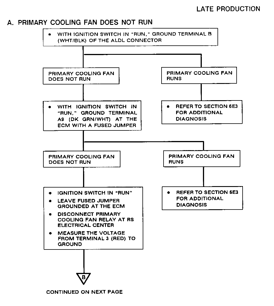
o If any diagnostic codes are present, refer to Section 6E3.
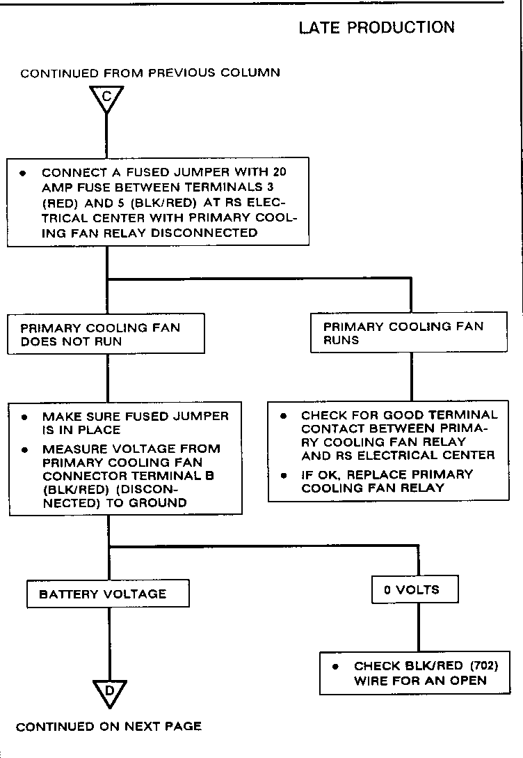
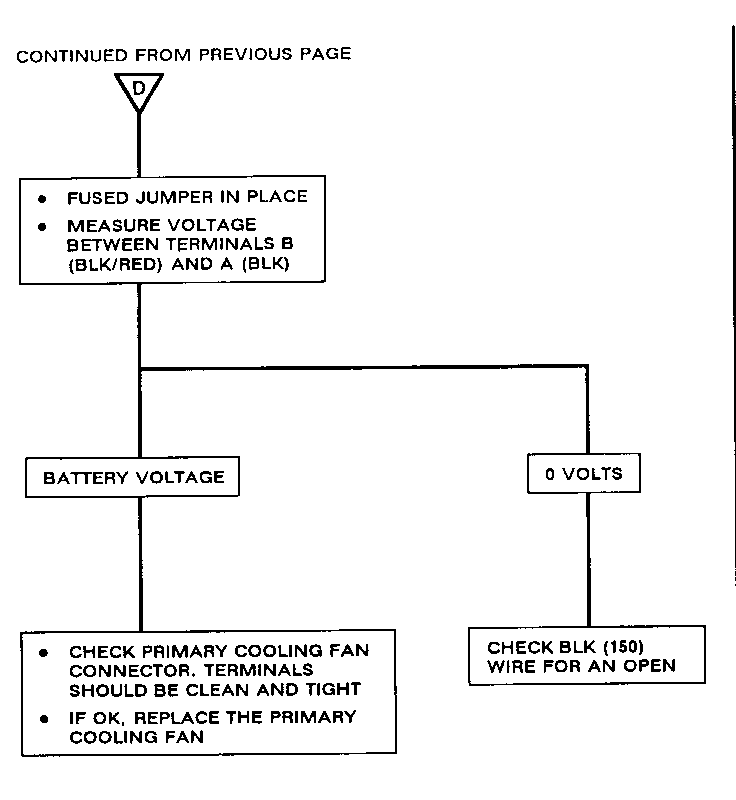
SYMPTOM TABLE FOR SYMPTOM DIAGNOSIS ---------------------------------- ----------- Primary Cooling Fan does not run Do Test A
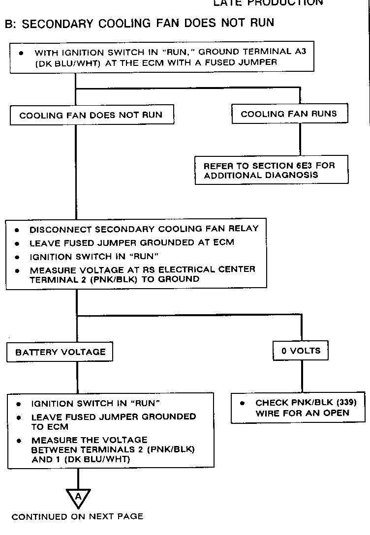
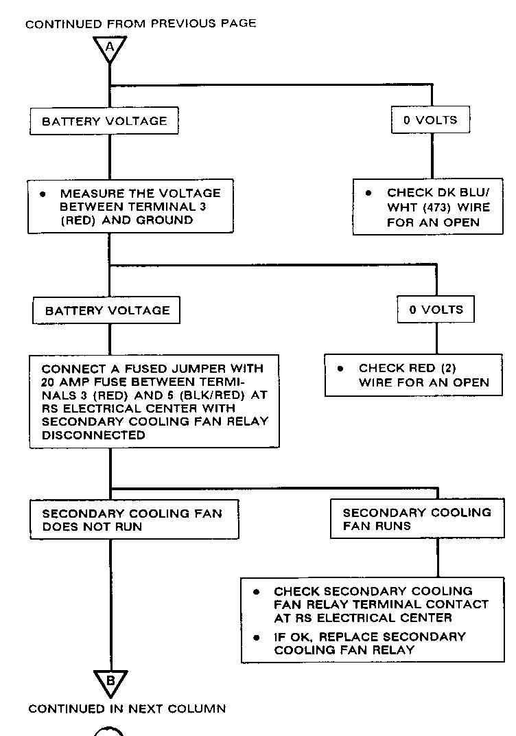
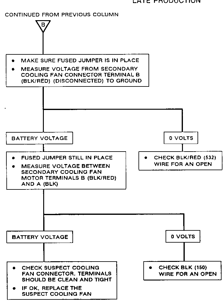
Secondary Cooling Fan does not run Do Test B
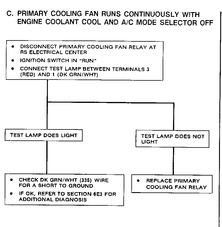
Primary Cooling Fan runs continuously with engine coolant cool and A/C mode Do Test C selector off
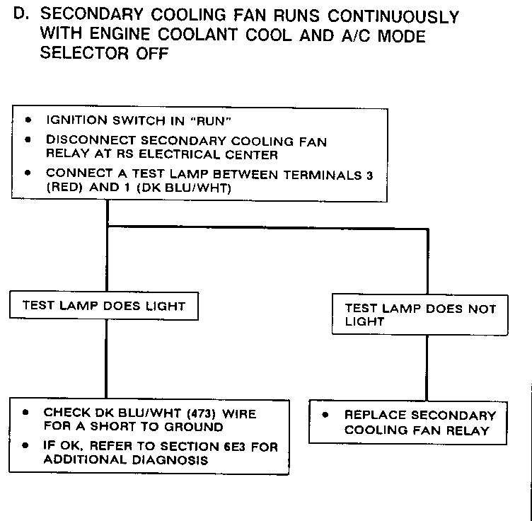
Secondary Cooling Fan runs continuously with engine coolant cool and A/C mode selector off Do Test D
CIRCUIT OPERATION
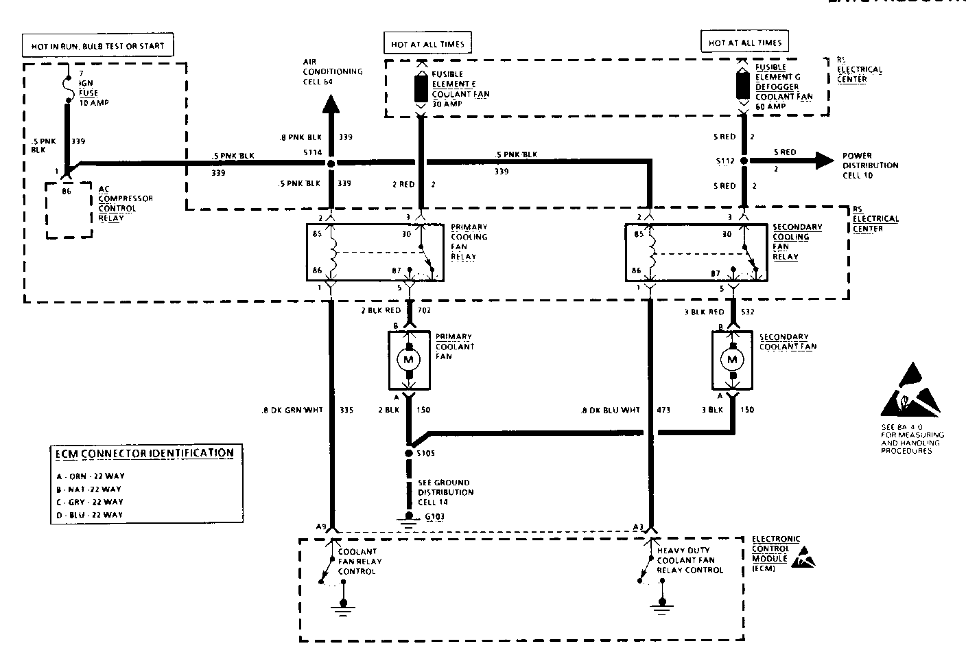
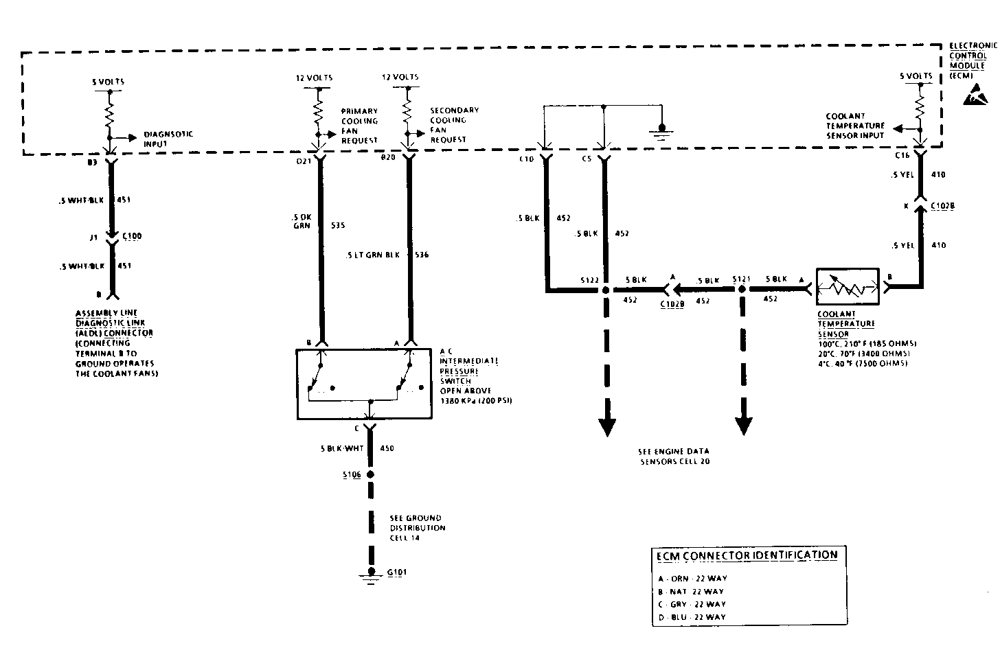
Each Cooling Fan is turned on and off by a separate Cooling Fan Relay.
The Primary Cooling Fan Relay coil is grounded through the ECM when vehicle speed is less than a speed determined by the ECM and the engine coolant reaches 108 C (227 F) with A/C off, and 106 C (223 F) with A/C on. The contacts close and voltage is applied through the Primary Cooling Fan Relay to the Primary Cooling Fan. The Primary Cooling Fan runs until the Ignition Switch is turned off, or coolant temperature decreases to 104 C (220 F) with A/C off, or 102 C (216 F) with A/C on.
The Secondary Cooling Fan Relay coil is grounded through the ECM when the coolant temperature reaches 118 C (245 F). The contacts close and voltage is applied to the Secondary Cooling Fan. The fan then runs at high speed and will continue to run at high speed with the Ignition in RUN until the coolant temperature lowers to 114 C (238 F).



General Motors bulletins are intended for use by professional technicians, not a "do-it-yourselfer". They are written to inform those technicians of conditions that may occur on some vehicles, or to provide information that could assist in the proper service of a vehicle. Properly trained technicians have the equipment, tools, safety instructions and know-how to do a job properly and safely. If a condition is described, do not assume that the bulletin applies to your vehicle, or that your vehicle will have that condition. See a General Motors dealer servicing your brand of General Motors vehicle for information on whether your vehicle may benefit from the information.
