SERVICE MANUAL UPDATE-SEC. 8A ELECTRONIC INSTRUMENT CLUSTER

VEHICLES AFFECTED: 1990 OLDSMOBILE W
The attached pages (Section 8A-80-0 through 8A-80-13) are revisions and additions for the following Service Manual. Please note your copies of the 1990 Oldsmobile Cutlass Supreme Service Manual.
ELECTRONIC INSTRUMENT CLUSTER: BASE
Component Location Page-Fig.
Coolant Level and Corrosivity Sensor Top RH rear side of radiator 201- 6-A Coolant Temperature Switch (VIN A) LH side of engine, near 201- 3-D (VIN D) coolant outlet Coolant Temperature Switch (VIN T)....LH rear of engine, near 201- 1-C coolant outlet Electronic Control Module (ECM) RH front engine compartment, 201- 5-B front of strut tower Fuel Pump/Oil Pressure Switch/Sender LH rear of engine, above 201- 3-E (VIN A) (VIN D) coolant outlet Fuel Pump/Oil Pressure Switch/Sender Front center of engine, .....201- 0-A (VIN T) near oil filter Fuel Tank Unit .......................Rear of car, in top of ...201-15-D fuel tank Fuse Block .. Behind RH side of I/P 201-10-A Generator (VIN A) (VIN D) ....RH front of engine ........201- 4-C Generator (VIN T) ...............Top RH side of engine 201- 2-A Ignition Switch ..................... RH side of steering column C100 (36 cavities) RH front of dash, behind .....201-10-A strut tower C102C (10 cavities) ...............RH front of engine compart- 201- 5-B ment, below RS Electrical Center C200(106 cavities) ...................Behind I/P, RH rear of dash 201-10-A C202(48 cavities) .Behind I/P, near steering ...201-10-A column C305(6 cavities) . Center rear of vehicle, near 201-15-A fuel tank G101(VIN A) (VIN D) Lower LH rear of engine 201- 3-F compartment, on top of transaxle G101(VIN T) ..........................Lower rear of engine, below 201- 2-B exhaust manifold G103(VIN A) (VIN D) Front of engine, below Starter Assembly G103(VIN T) ......................... LH Front of engine compart- 201- 8-A ment, on radiator support S122..................................Engine harness, RH front of 201- 5-B engine compartment S206..................................I/P harness, behind center ..201-12-C of I/P S209..................................I/P harness, behind center....201-10-A of I/P S211..................................I/P harness, behind center ..201-10-A of I/P S213..................................I/P harness, behind RH side .201-12-B of I/P S232..................................I/P harness, behind center ...201-10-A of I/P S247..................................I/P harness, behind LH side...201-10-A of I/P S288..................................I/P harness, behind center ..201-10-A of I/P
TROUBLESHOOTING HINTS
Try the following checks before doing the System Check.
1. If none of the Warning Indicators operate, check INDIC Fuse.
2. If Illumination Lights do not operate, check PANEL Fuse.
3. If more than one indicator is out, check the battery voltage and ground inputs common to all affected indicators.
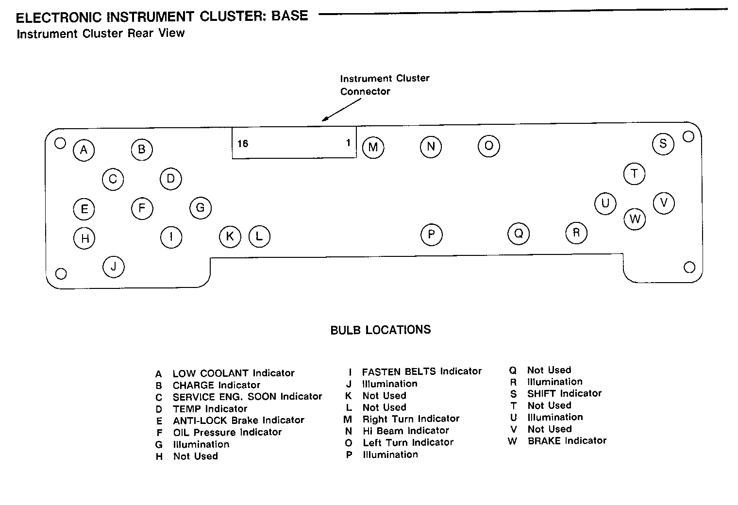
4. Check bulbs.
5. If Speedometer, Odometer and Fuel Gage do not operate, check CLUST Fuse.
6. If Trip Odometer does not operate properly, check ELEC Fuse.
Go to System Check for a guide to normal operation.
Go to System Diagnosis for diagnostic tests.
SYSTEM CHECK
For Instrument Cluster removal and replacement procedures, see Section 8C.
Use the System Check Table as a guide to normal operation. Refer to the diagnosis given if other results occur.
Tests follow in System Diagnosis.
SYSTEM CHECK TABLE
ACTION NORMAL RESULT FOR DIAGNOSIS OF OTHER RESULTS
Turn Ignition Switch to RUN All Vacuum Fluorescent If some, but not all (driver's door closed) segments light segments light, replace the Instrument Cluster (see Section 8C)
All Vacuum Fluorescent Replace Instrument segments revert to Cluster (see Section true readings in less 8C) than 3 seconds time The SERVICE ENGINE SOON See Section 6E of the Indicator lights Service Manual The FASTEN BELTS See Warnings and Alarms Indicator lights Schematic, until driver's safety Section 8A-76 belt is buckled The OIL Pressure Do Test F Indicator lights LOW COOLANT Indicator See Section 6E2 or 6E3 lights CHARGE Indicator is on See Section 8A-30
ANTI-LOCK Indicator See Anti-Lock Brakes, lights briefly (if Section 8A-44 equipped)
Press the English/Metric The Speedometer and button twice Odometer switch between and Metric values
The Driver Information speed and distance See Symptom Table displays switch between English and Metric values
The Heater And A/C Control Assembly (C68 only) temperature display values switch between degrees Fahrenheit and Centigrade.
Turn on the Park Lights All Displays are dimmed Do Test A check (Ignition Switch in RUN) to the present dimmer terminals C6 and control setting and C3 Cluster Illumination Lights come on
Adjust the Dimmer Control The cluster brightness Do Test A check in both directions changes terminals C7 and (Ignition Switch in RUN) C3
Turn the Headlights to Hi The Hi Beam Indicator Do Test A check Beams and then to off lights when the Hi Beams terminal D5 (Ignition Switch in RUN) are on
Apply the Park Brake The BRAKE Indicator See Brake Warning (Ignition Switch in RUN) lights System Schematic, Section 8A-41 Operate the Turn Signals Indicators flash with Do Test A check in both directions the turn lights terminal D4 and (Ignition Switch in RUN) D6
SYSTEM DIAGNOSIS Do the tests listed for your Tests follow the Symptom symptom in the Symptom Table Table. below, or when directed by the System Check.
SYMPTOM TABLE
SYMPTOM FOR DIAGNOSIS
Speedometer and Odometer See Vehicle Speed Sensor, Section 8A-33 are both inaccurate Speedometer and Odometer See Vehicle Speed Sensor, Section 8A-33 do not work Either Speedometer or Replace the Instrument Cluster, see Section Odometer does not work 8C Trip Odometer does not Replace the Instrument Cluster, see Section reset 8C Cluster Illumination See Interior Lights Dimming, Section 8A-117 Lights do not work (also see Test A, terminal C3) Fuel Gage always reads E Do Test B (also, see Test A, terminal C4)
Fuel Gage always reads F Do Test C(also, see Test A, terminal C4)
Fuel Gage is inaccurate Do Test D(also, see Test A, terminal C4)
CHARGE Indicator does not See Starter and Charging System, Section work properly 8A-30 OIL Pressure Indicator is Do Test E(also, see Test A, terminal D11) always lit OIL Pressure Indicator does Do Test F(also, see Test A, terminal D11) not light with Ignition Switch in RUN (engine not running)
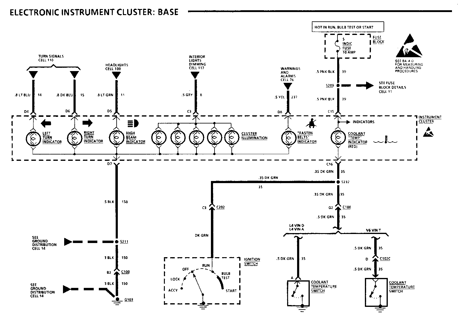
Coolant TEMP Indicator does Do Test H(also, see Test A, terminal C16) not light in BULB TEST
Coolant TEMP Indicator is on Do Test G(also, see Test A, terminal C16) when engine is not overheated Coolant TEMP Indicator does not Do Test I (also, see Test A, terminal C16) light when engine is overheated BRAKE Indicator does not work See Brake Warning System, Section 8A-41 properly (also, see Test A, terminal C1) SERVICE ENGINE SOON Indicator See Section 6E2 or 6E3 does not work properly SHIFT Indicator does not See Section 6E2 or 6E3 work properly Hi Beam Indicator does not See Headlights, Section 8A-100 (also, work properly see Test A, terminal D5) Turn Indicators do not See Exterior lights, Section 8A-110 work properly (also, see Test A, terminal D4 and D6) FASTEN BELTS Indicator does See Warnings and Alarms, Section 8A-76 not work properly (also, see Test A, terminal D8)
LOW FUEL Indicator does not Replace the Instrument Cluster light with 3 bars lit (see Section 8C)
LOW FUEL Indicator does not Replace the Instrument Cluster flash with only 1 bar lit (see Section 8C)
LOW FUEL Indicator is lit Replace the Instrument Cluster when 4 or more bars are (see Section 8C) lit or flashes when 2 or more bars are lit
ANTI-LOCK Indicator does not See Anti-Lock Brakes, Section 8A-44 work properly
LOW COOLANT Indicator does not See Section 6E2 or 6E3 work properly
Speedometer/Odometer speed and Do Test J distances do not change between English and Metric values when the Instrument Cluster English/Metric Switch is pressed
Driver Information System and Check the LT BLU (811) wire for an open. distances do not change between If OK, replace the Driver Information System English and Metric values when the Instrument Cluster English/ Metric Switch is pressed. Instrument Cluster Speedometer does not change correctly
Heater and A/C Control Assembly Check the LT BLU (811) wire for an open. (C68 only) temperatures do not If OK, replace the Heater And A/C change between F and C when the Control Assembly Instrument Cluster English/Metric switch is pressed. Instrument Cluster Speedometer does not change correctly
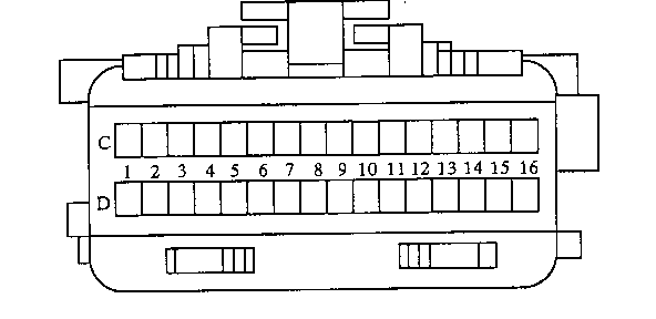
A: INSTRUMENT CLUSTER CONNECTOR PIN-OUT TEST
Measure all voltages to ground with the ignition Switch in RUN.
Measure all resistances to ground with the Ignition Switch OFF and negative Battery Cable Disconnected.
Check all ground terminals with a self-powered test lamp before making voltage or resistance measurements. Cluster connector as seen from the driver's seat with cluster removed.
If the correct voltage or resistance is found at the terminal, and the function that uses that terminal does not operate and all appropriate incandescent bulbs have been checked, replace the Instrument Cluster. (See Section 8C)
INSTRUMENT CLUSTER CONNECTOR TERMINALS C1-D16
Terminal/ Function Wire
C1 To BRAKE Indicator. Indicator is grounded when Park Brake is on (TAN/WHT 33) or brake fluid is low. Infinite ohms with Park Brake off. See Section 8A-41 C2 NOT USED
C3 Illumination Bulbs Dimmer Input. Variable voltage with lights on (GRY 8) and dimmer adjusted. See Section 8A-117
C4 Fuel Gage Sender Input. 86 ohms, Full (16 Bars lit), 11 ohms, (PPL 30) Empty (1 Bar lit), 8 ohms, Empty (O Bars lit) Do Tests B, C and D
C5 Vehicle Speed Input from ECM. See Section 8A-33 (DK GRN 389)
C6 VF Dim Enable Input. Battery voltage when Park Lights or (YEL 726) Headlights are On. See Section 8A-12
C7 VF Dimmer Input. Variable voltage with lights on and dimmer (BRN/WHT adjusted. See Section 8A-117. 230)
C8 Battery Input. Battery voltage at all times. See Section 8A-11 (ORN 640)
C9 Englich/Metric switch output to Driver Information System, HUD (LT BLU 811)Unit, and Heater and A/C Control Assembly. Do Test J
C10 Ground to G101. See Section 8A-14. (BLK 151)
C11 NOT USED
C12 NOT USED
C13 Battery Power to VF displays. Battery Voltage in RUN. (PNK/BLK 750)See section 8A-11.
C14 NOT USED
C15 Ignition Power to the Indicators. Battery Voltage in RUN, BULB (PNK/BLK 39) TEST or START. See Section 8A-11.
C16 To Coolant TEMP Indicator. Grounded with engine overheated or (DK GRN 35) with Ignition Switch in BULB TEST. Normally open. Do Tests G, H and I
D1 NOT USED
D2 NOT USED
D3 To SHIFT Indicator, ECM provides a ground for the Indicator. (TAN/BLK456)
D4 To Left Turn Indicator. Flashing battery voltage with Left (LT BLU 14) Turn Signal. See Section 8A-110.
D5 To Hi Beam Indicator. Battery voltage with Hi Beams ON. (LT GRN 11) See Section 8A-100
D6 To Right Turn Indicator. Flashing battery voltage with Right (DK BLU 15) Turn Signal. See Section 8A-110.
INSTRUMENT CLUSTER CONNECTOR TERMINALS C1-D16
D7 Ground. See Section 8A-14 (BLK 150) D8 FASTEN BELTS Indicator. Battery voltage with safety belts (YEL 237) unbuckled Ignition is switched to RUN. See Section 8A-76
D9 NOT USED
D10 NOT USED
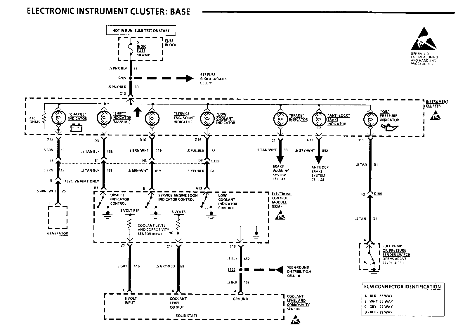
D11 To OIL Pressure Indicator. Oil Pressure Switch grounds the (TAN 31) Indicator with low oil pressure. Do Tests E and F
D12 NOT USED
D13 To ANTI-LOCK Indicator. See Anti-Lock Brake System, Section 8A-44 (GRY/WHT 852)
D14 To LOW COOLANT Indicator. ECM provides ground when the coolant (YEL/BLK 68) level is low
D15 To CHARGE Indicator. See Section 8A-30 (BRN 25)
D16 To SERVICE ENGINE SOON Indicator. ECM provides a ground for the (BRN/WHT 419) Indicator. See Section 6E
B: FUEL GAGE ALWAYS READS E
Open C305. Move Ignition Switch to RUN and observe the Fuel Gage,
If the Fuel Gage now reads F, replace the Fuel Gage Sender.
If the Fuel Gage still shows E, check PPL (30) wires for a short to ground (see schematic). If PPL (30) wires are good, replace the Instrument Cluster (see Section 8C).
C: FUEL GAGE ALWAYS READS F
Disconnect C305 and jumper harness half, terminal B (PPL) to ground. Move Ignition Switch to RUN and observe the Fuel Gage.
If the Fuel Gage now reads E, check BLK/ WHT (151) wire for an open (see schematic). If wire is OK, replace Fuel Gage Sender.
If the Fuel Gage still reads F, check PPL (30) wire for an open (see schematic). If PPL (30) wire is good, replace the Instrument Cluster (see Section 8C).
D: FUEL GAGE ACCURACY TEST
Open C305 and connect the two red clip leads of tester J33431 to terminals E (BLK) and B (PPL) of the harness half of that connector. With the Ignition in RUN, set the resistance dial on the tester to 11 ohms (1 bar lit), 46 ohms (8 bars lit), and 87 ohms (16 bars lit).
Turn the ignition off and on after changing resistance settings. Observe the Fuel Gage.
If the Gage responds correctly, install a new Fuel Gage Sender.
If the Gage does not respond correctly, check PPL (30) and BLK (151) wires for high resistance. If all checks are OK, replace the Instrument Cluster (see Section 8C).
E: OIL PRESSURE INDICATOR IS ALWAYS ON
1. Check oil level and pressure with a mechanical gage.
If oil level and pressure are OK, go to Step 2.
If oil level and pressure are not OK, see Section 6 for diagnosis.
2. With Ignition Switch in RUN, disconnect the Oil Pressure Switch connector.
If the OIL Pressure Indicator is now out, replace the Oil Pressure Switch.
If the OIL Pressure Indicator is still on, check/repair TAN (31) wire for a short to ground (see schematic). If all checks are OK, replace the Instrument Cluster (see Section 8C).
F: OIL PRESSURE INDICATOR DOES NOT LIGHT WITH THE IGNITION SWITCH IN RUN (ENGINE NOT RUNNING)
Connect: FUSED JUMPER
At: OIL PRESSURE SWITCH CONNECTOR (Disconnected)
Condition:
Ignition Switch: RUN
Jumper Correct For Between Result Diagnosis
TAN & OIL Ground (see Pressure See 1 Indicator schematic lights
If the OIL Pressure Indicator comes on, replace the Oil Pressure Switch.
1. Check/Repair TAN (31) wire for an open (see schematic). If OK, replace the Instrument Cluster.
G: COOLANT TEMP INDICATOR IS ON AT ALL TIMES
Disconnect the Coolant Temperature Switch connector. Put Ignition Switch in RUN and observe the Coolant TEMP Indicator.
If the Indicator does not light, replace the Coolant Temperature Switch.
If the Indicator is still on, check DK GRN (35) wires and the Ignition Switch for a short to ground (see schematic). If wires are OK, replace the Instrument Cluster (see Section 8C).
H: COOLANT TEMP INDICATOR DOES NOT LIGHT WITH IGNITION SWITCH BULB TEST
Connect: FUSED JUMPER
At: CONNECTOR C202 (Connected)
Condition:
Ignition Switch: RUN (after the jumper is connected)
Jumper Correct For Between Result Diagnosis
C3 (DK Coolant GRN) & TEMP See 1 Ground Indicator
If the Coolant TEMP Indicator lights, replace the Ignition Switch.
1. Check DK GRN (35) wire for an open (see schematic).
I: COOLANT TEMP INDICATOR DOES NOT LIGHT WHEN ENGINE OVERHEATS
Disconnect the Coolant Temperature Switch and jumper DK GRN (35) wire to ground. Move Ignition Switch to RUN and observe the Coolant TEMP Indicator.
If the Indicator now lights, replace the Coolant Temperature Switch.
If the Indicator does not light, check DK GRN (35) wires for an open (see schematic). If wires are OK, replace the Instrument Cluster (see Section 8C).
J: E/M SWITCH OUTPUT TEST
1. Disconnect the instrument Cluster connector. Put the Ignition Switch in RUN and observe the Driver information System.
If the speed and distance values are in English, go to step 2.
If the speed and distance values are in Metric, check the LT BLU (811) wire, Driver Information System, HUD Unit and Heater And A/C Control Head (C68 only) for a short to ground. Replace/repair as necessary.
2. With the Ignition Switch in RUN, connect a fused jumper between the Instrument Cluster connector terminal C9 and ground. Observe the Driver Information System.
If the speed and distance values are displayed in Metric, replace the Instrument Cluster.
If the fuse in the jumper blows, check the LT BLU (811) wire, Driver Information System, HUD Unit and Heater And A/C Control Head (C68 only) for a short to battery. Replace/repair as necessary.
If the speed and distance values are not displayed in Metric, check the LT BLU (811) wire for an open. Check the Driver Information System and Heater And A/C Control Head (C68 only) and HUD Unit for a short to battery. Replace/repair as necessary.
CIRCUIT OPERATION FUEL GAGE
The Fuel Gage is a vacuum fluorescent bar display which is controlled by a microprocessor within the cluster. The cluster reads an analog resistance signal from the Fuel Gage Sender and converts this signal into a digital signal used by the bar graph display. The Fuel Gage Sender is variable resistor. Its resistance is approximately 90 ohms with a full tank and approximately 1 ohm with an empty tank.
COOLANT TEMP INDICATOR
The Coolant TEMP Indicator receives battery voltage with the Ignition Switch in RUN, BULB TEST or START. The indicator is grounded by the Coolant Temperature Switch with the coolant above 258 DEG F (126 DEG C). This indicator is also grounded by the Ignition Switch with the Ignition Switch in BULB TEST, or START as a bulb check.
SPEEDOMETER/ODOMETER
The Speedometer and Odometer are digital displays controlled by a microprocessor within the Instrument Cluster. The Cluster receives a ve- hicle speed signal from the ECM in the form of voltage pulses. The frequency of these pulses is 4000 pulses per mile. The ECM receives its speed signal from the Vehicle Speed Sensor.
ENGLISH/METRIC FUNCTION
The English/Metric Switch contols an output to the Driver Information System (DIS), Heater And A/C Control Assembly and the Head Up Display (HUD) Unit. With the cluster in the English mode the 811 wire is pulled up to ignition voltage by the cluster and the other components sharing the 811 wire. When the cluster is in the Metric mode, the cluster grounds the wire, forcing all modules to display metric values. The DIS also has an English/Metric button, which only controls the DIS display.
OIL PRESSURE INDICATOR
The OIL Pressure Indicator comes on to warn the driver when the engine oil pressure is low. Battery voltage is applied to one side of the bulb. A ground path is provided by the Oil Pressure Switch. It closes when the oil pressure is below 27kPa (4 PSI) and the Indicator bulb lights. After the engine starts and normal oil pressure builds up, the Oil Pressure Switch opens. The OIL Pressure Indicator goes out.


General Motors bulletins are intended for use by professional technicians, not a "do-it-yourselfer". They are written to inform those technicians of conditions that may occur on some vehicles, or to provide information that could assist in the proper service of a vehicle. Properly trained technicians have the equipment, tools, safety instructions and know-how to do a job properly and safely. If a condition is described, do not assume that the bulletin applies to your vehicle, or that your vehicle will have that condition. See a General Motors dealer servicing your brand of General Motors vehicle for information on whether your vehicle may benefit from the information.
