SERVICE MANUAL UPDATE-SEC.6E3 REVISED CODE 62 FACING

SUBJECT SERVICE MANUAL UPDATE - SECTION 6E3 - DRIVEABILITY AND EMISSIONS, REVISED CODE 62 FACING PAGE AND CHART, CHART C-8A FACING PAGE, ECM WIRING DIAGRAM (3 OF 3) AND SECTION 8A MODELS/YEARS 1990 CUTLASS CALAIS AND CUTLASS SUPREME WITH 2.3L (VIN D)
CORPORATION REFERENCE NUMBERS: 916525R 916532 916533 038125
This bulletin cancels and supersedes Dealer Technical Bulletin 90-T-16 which may be discarded. This revision includes proper location of the second gear switch, labeling the ECM connector GF4, removal of VIN A engine application and clarification of the code 62 chart.
This bulletin serves to update the following service manual pages:
1990 CUTLASS CALAIS SERVICE MANUAL Section 6E3 "Driveability and Emissions": ---------------------------------------------------------------------------
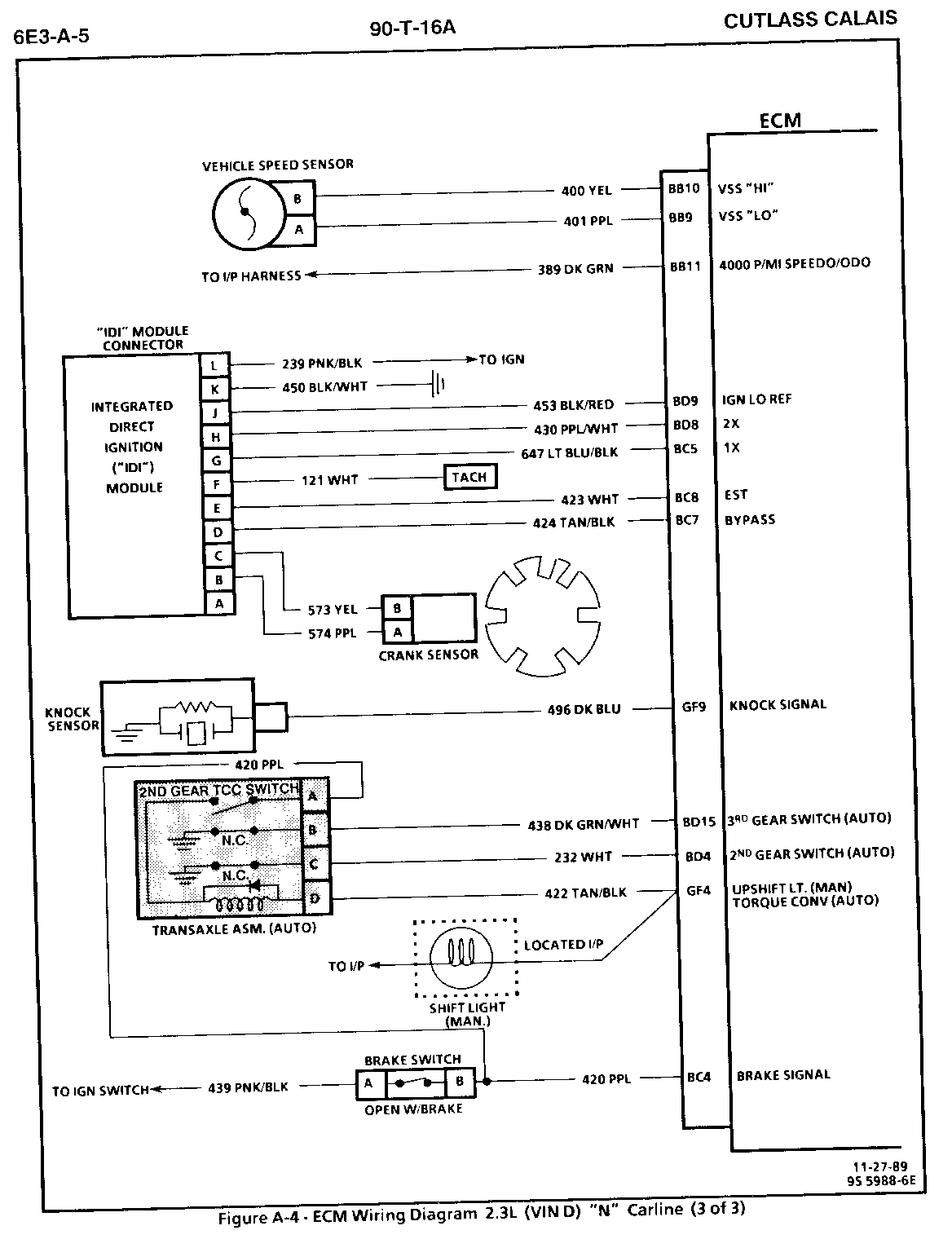
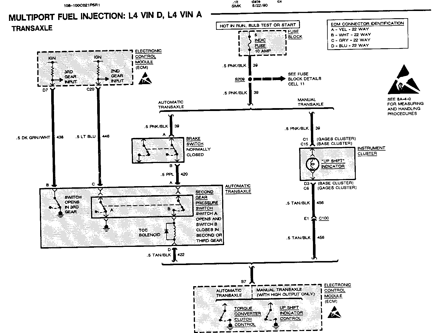
- ECM wiring diagram (page 3 of 3) on page 6E3-A-5
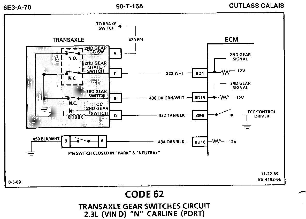
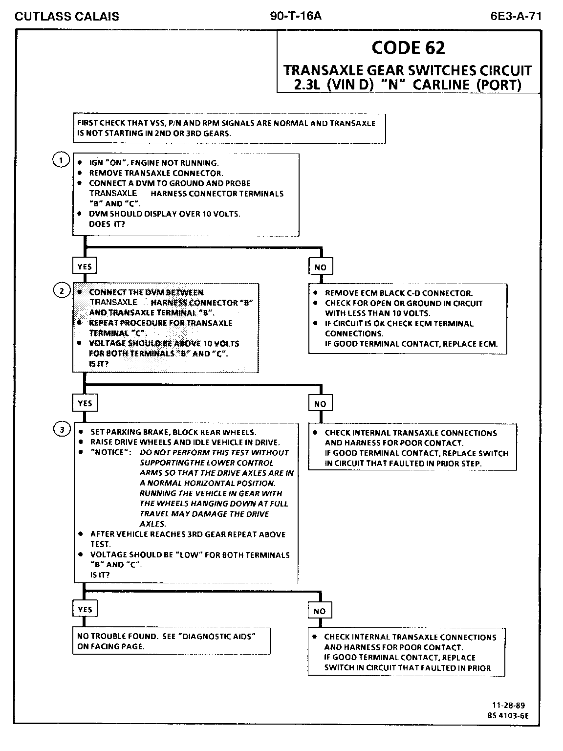
- Code 62 chart and facing page on page 6E3-A-70 and 71
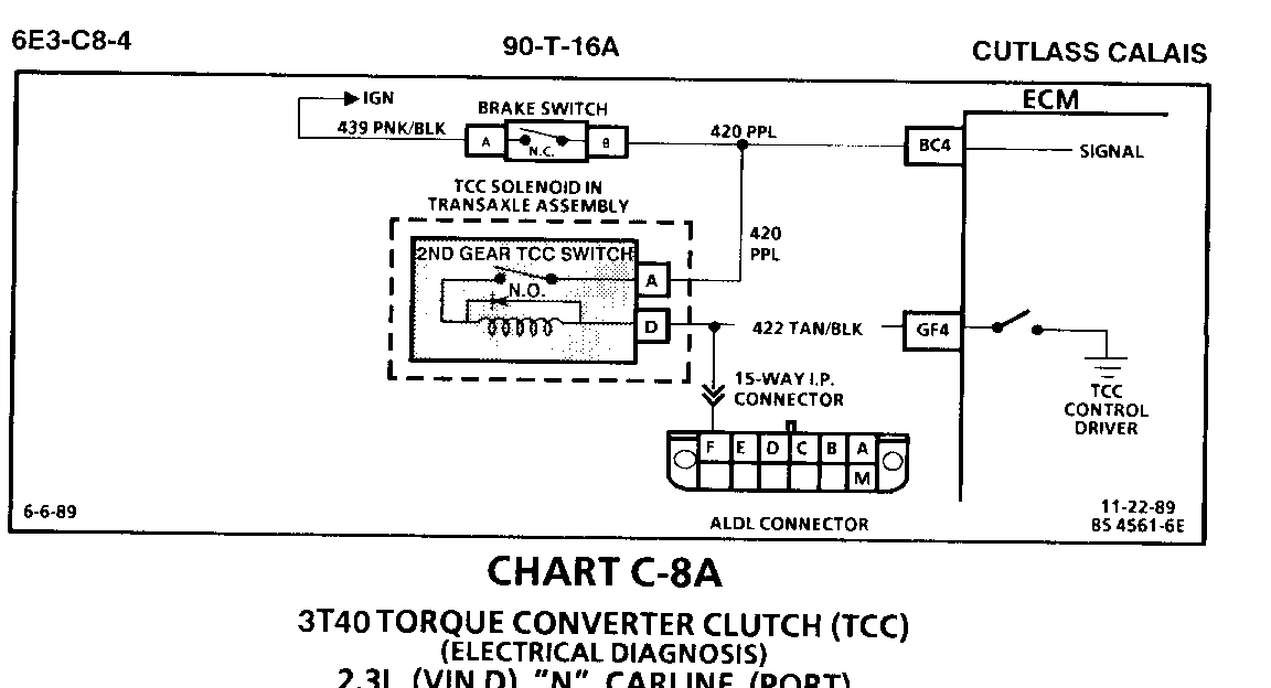
- Chart C-8A facing page on page 6E3-C8-4
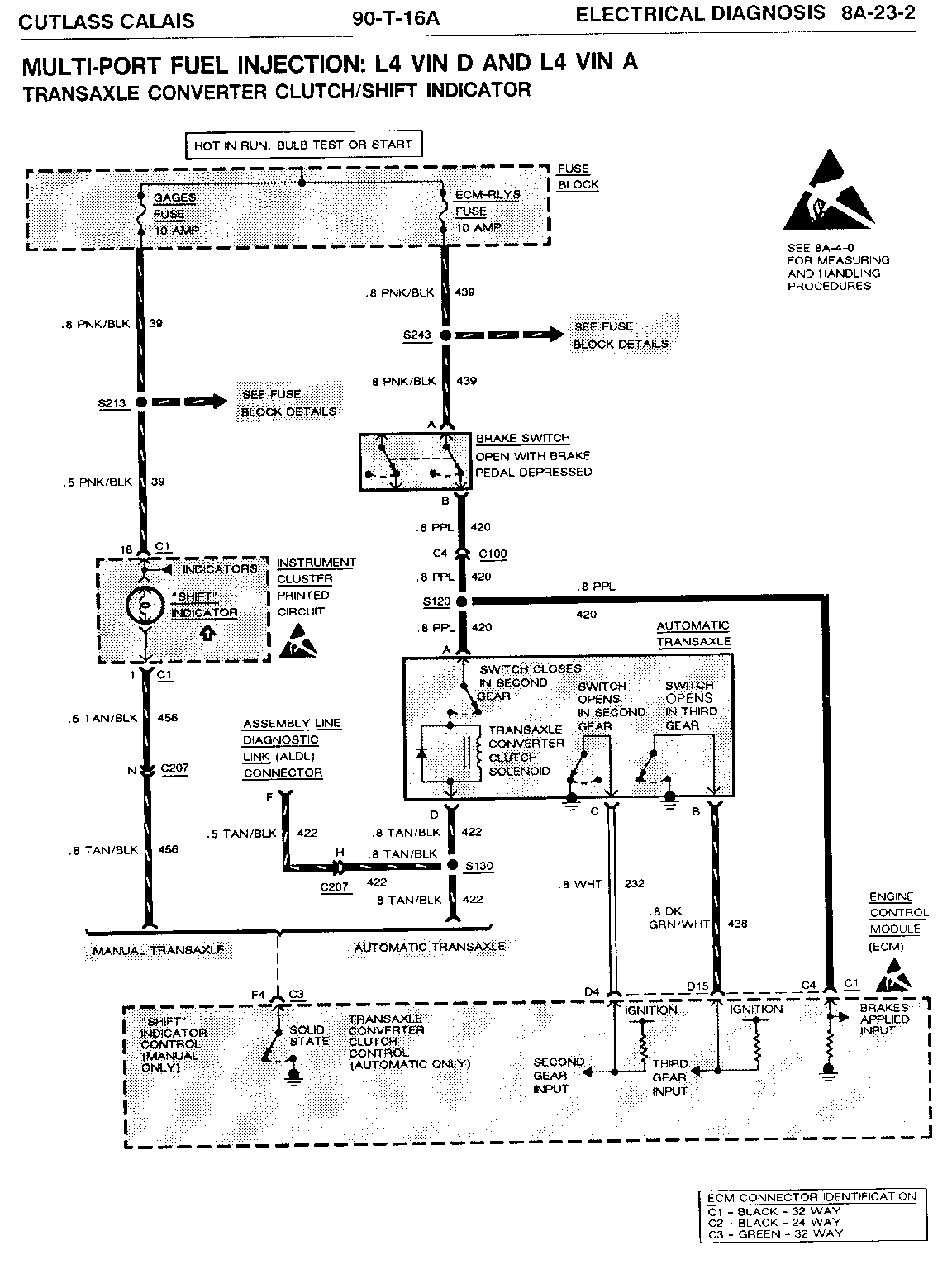
- Page 8A-23-2 change statement above automatic transaxle "third" gear switch to read "Opens in Third Gear" and should be shown as a normally closed switch (N.C.)
1990 CUTLASS SUPREME SERVICE MANUAL Section 6E3 "Driveability and Emissions": ---------------------------------------------------------------------------
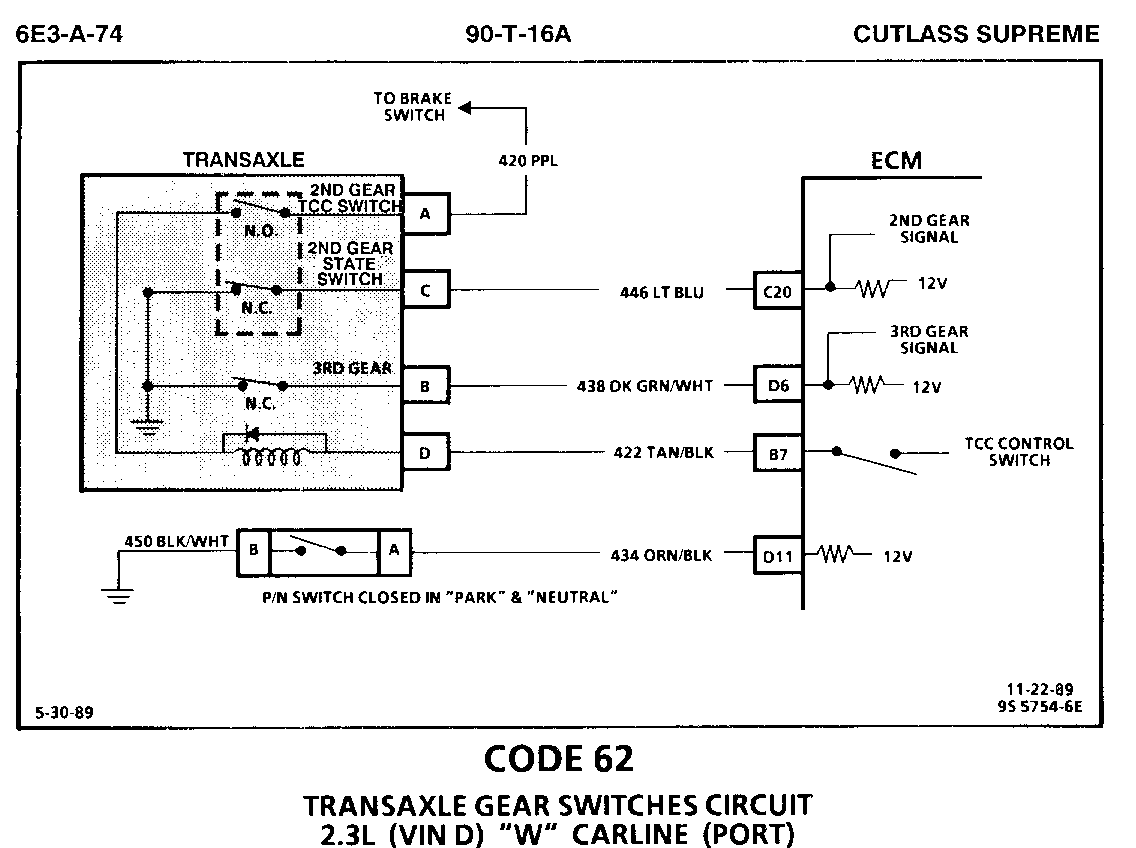
- Code 62 chart and facing page on page 6E3-A-74 and 75
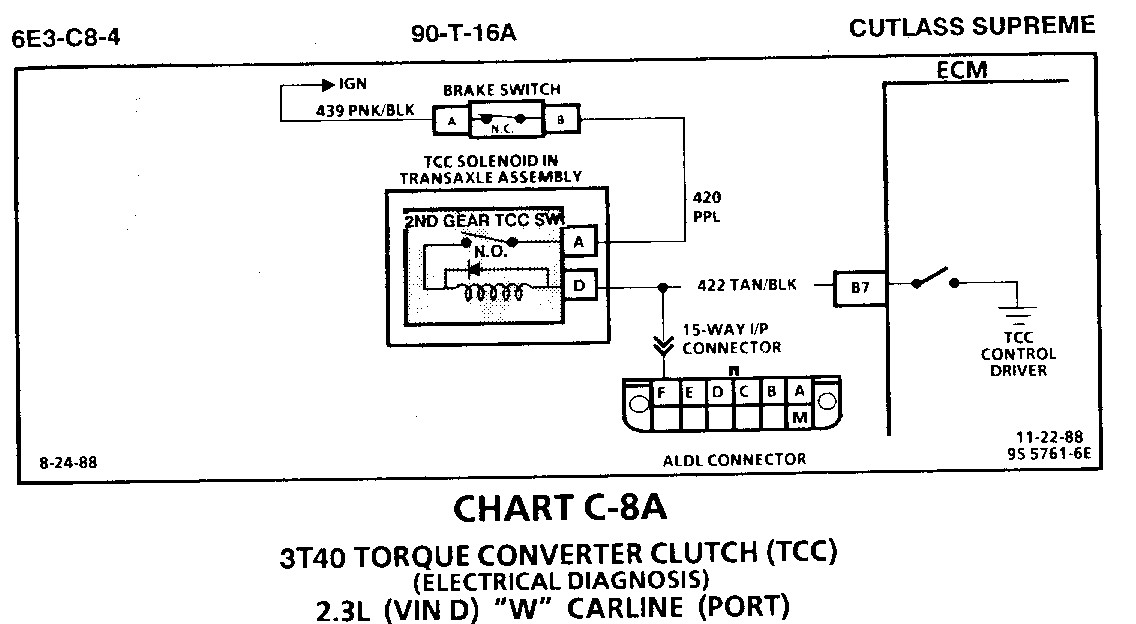
- Chart C-8A facing page on page 6E3-C8-4
- Page 8A-21-5 automatic transaxle status switches were drawn and labeled incorrectly. Page 8A-21-5 of this bulletin shows the correct identification.
Please mark a reference to this bulletin in your service manuals.
Circuit Description:
Code 62 diagnostic is used to check the 2nd and 3rd gear switch inputs to the ECM. Transaxle gear input signals to the ECM are determined as follows:
1st gear = 2nd gear switch closed (also P/N & R) 3rd gear switch closed 2nd gear = 2nd gear switch open 3rd gear switch closed 3rd gear = 2nd gear switch open 3rd gear switch open
Test Description: Numbers below refer to circled numbers on the diagnostic ----------------- chart.
Code 62 will set if any of the following conditions are met for approximately 17 seconds:
o In "PARK" or "NEUTRAL" and 2nd or 3rd gear indicated.
o Vehicle speed less than approximately 5 mph and 2nd or 3rd gear indicated.
o First or second gear indicated, less than approx. 3000 rpm, not in P/N, and VSS greater than 50 mph.
o Vehicle at operating temperature.
1. Step one checks for an open or grounded circuit between transaxle connector and ECM. Since the ECM terminals are normally high, B+ should be indicated at both terminals with the connector removed.
2. The DVM should measure near B+ because the 2nd and 3rd gear switches should provide continuity to ground.
3. The third step checks to see if the transaxle switches function normally. In third gear both switches should have changed from their original 1st gear state.
Diagnostic Aids:
Clear codes and recheck for Code 62. If code resets, check all harness connections, VSS, rpm, P/N circuits prior to replacing an, ECM. Transmission starting in 2nd or 3rd gear or a sticky 2nd gear switch can also cause Code 62.
Circuit Description:
The purpose of the Torque Converter Clutch (TCC) feature is to eliminate the power loss of the transaxle converter stage when the vehicle is in a cruise condition. This allows the convenience of the automatic transaxle and the fuel economy of a manual transaxle.
Fused battery ignition is supplied to the TCC solenoid through the brake switch, and transaxle 2nd gear apply switch. The ECM will engage TCC by grounding CKT 422 to energize the solenoid.
TCC will engage when:
o Vehicle speed above a calibrated value (about 34 mph) (55 km/h).
o Throttle position sensor output not changing, indicating a steady road speed.
o Transaxle second gear switch closed.
o Brake switch closed.
Test Description: Numbers below refer to circled numbers on the diagnostic ---------------- chart.
1. Light "OFF" confirms transaxle second gear apply switch is open.
2. By 25 mph, the transaxle second gear TCC switch should close. Test light will come "ON" and confirm battery supply and closed brake switch.
3. Grounding the diagnostic terminal with ignition "ON," engine "OFF," should energize the TCC solenoid by grounding CKT 422. This test checks the ability of the ECM to supply a ground to the TCC solenoid. The test light connected from 12 volts to ALDL terminal "F" will turn "ON" as CKT 422 is grounded.
Diagnostic Aids:
A "Scan" tool only indicates when the ECM has turned "ON" the TCC driver and this does not confirm that the TCC has engaged. To determine if TCC is functioning properly, engine rpm should decrease when the "Scan" indicates the TCC driver has turned "ON."
Circuit Description:
Code 62 diagnostic is used to check the 2nd and 3rd gear switch inputs to the ECM. Transaxle gear input signals to the ECM are determined as follows:
1st gear = 2nd gear switch closed (also P/N & R) 3rd gear switch closed 2nd gear = 2nd gear switch open 3rd gear switch closed 3rd gear = 2nd gear switch open 3rd gear switch open
Test Description: Numbers below refer to circled numbers on the diagnostic ----------------- chart.
Code 62 will set if any of the following conditions are met for approximately 17 seconds:
o In "PARK" or "NEUTRAL" and 2nd or 3rd gear indicated.
o Vehicle speed less than approximately 5 mph and 2nd or 3rd gear indicated.
o First or second gear indicated, less than approximately 3000 rpm, not in P/N, and VSS greater than 50 mph.
o Vehicle at operating temperature.
1. Step one checks for an open or grounded circuit between transaxle connector and ECM. Since the ECM terminals are normally high, B+ should be indicated at both terminals with the connector removed.
2. The DVM should measure near B+ because the 2nd and 3rd gear switches should provide continuity to ground.
3. The third step checks to see if the transaxle switches function normally. In third gear both switches should have changed from their original lst gear state.
Note On Intermittents
Clear codes and recheck for Code 62. If code resets, check all harness connections, VSS, rpm, P/N circuits prior to replacing an ECM. Transaxle starting in 2nd or 3rd gear can also cause Code 62. Refer to Section "7" for transaxle diagnosis information.
Circuit Description:
The purpose of the torque converter clutch feature is to eliminate the power loss of the stage when the vehicle is in a cruise condition. This allows the convenience of the automatic transaxle and the fuel economy of a manual transaxle.
Fused battery ignition is supplied to the TCC solenoid through the brake switch, and transaxle 2nd gear apply switch. The ECM will engage TCC by grounding CKT 422 to energize the solenoid.
TCC will engage when:
o Vehicle speed above a calibrated value (about 34 mph) (55 km/h).
o Throttle position sensor output not changing, indicating a steady road speed.
o Transaxle second gear switch closed.
o Brake switch closed.
Test Description: Numbers below refer to circled numbers on the diagnostic ----------------- chart.
1. Light "OFF" confirms transaxle second gear apply switch is open.
2. By 25 mph, the transaxle second gear TCC switch should close. Test light will come "ON" and confirm battery supply and closed brake switch.
3. Grounding the diagnostic terminal with ignition "ON," engine "OFF," should energize the TCC solenoid by grounding CKT 422. This test checks the ability of the ECM to supply a ground to the TCC solenoid. The test light connected from 12 volts to ALDL terminal "F" will turn "ON" as CKT 422 is grounded.
Diagnostic Aids:
A "Scan" tool only indicates when the ECM has turned "ON" the TCC driver and this does not confirm that the TCC has engaged. To determine if TCC is functioning properly, engine rpm should decrease when the "Scan" indicates the TCC driver has turned "ON."

General Motors bulletins are intended for use by professional technicians, not a "do-it-yourselfer". They are written to inform those technicians of conditions that may occur on some vehicles, or to provide information that could assist in the proper service of a vehicle. Properly trained technicians have the equipment, tools, safety instructions and know-how to do a job properly and safely. If a condition is described, do not assume that the bulletin applies to your vehicle, or that your vehicle will have that condition. See a General Motors dealer servicing your brand of General Motors vehicle for information on whether your vehicle may benefit from the information.
