SERVICE MANUAL UPDATE SEC. 3C TOOL FOR STRUT CART. REMOVAL

SUBJECT: SERVICE MANUAL UPDATE NEW SPECIAL TOOL AND REVISE PROCEDURE FOR STRUT CARTRIDGE REMOVAL
MODELS/YEARS: 1988-91 CUTLASS SUPREME
Please mark a reference to this bulletin in the following Cutlass Supreme Service Manuals; 1988 page 3C-1, 1989 and 1990 page 3C-3 and 1991 page 3C-2.
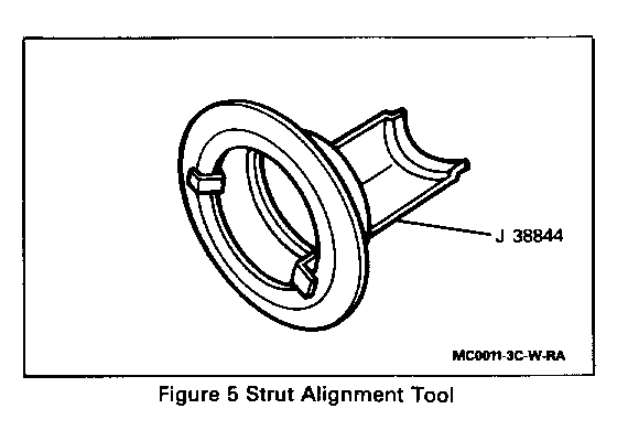
The following procedure has been revised to include a new special tool, J 38844. J 38844 will be shipped as part of the 1991 Essential Tool Program. This tool was developed to eliminate the possibility of the front suspension spring moving out of alignment when removing the strut cartridge. STRUT CARTRIDGE
Tools Required: J 38844 Strut Alignment Tool, J 35668 Strut Extension Rod, J 35669 Strut Rod Nut Remover and Installer, and J 35671 Strut Cap Nut Wrench.
CAUTION:
Do not service the strut cartridge unless the weight of the vehicle is on the suspension. The weight of the vehicle keeps the coil spring compressed, otherwise the released coil spring could cause personal injury.
Remove or Disconnect:
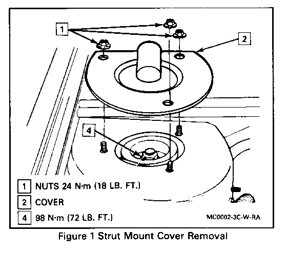
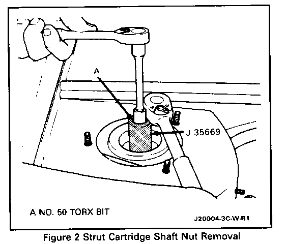
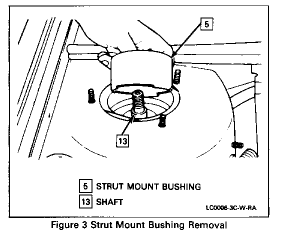
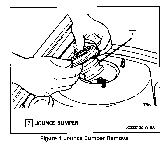
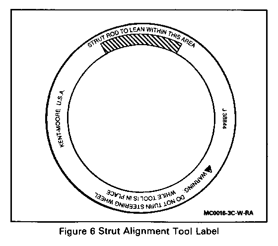
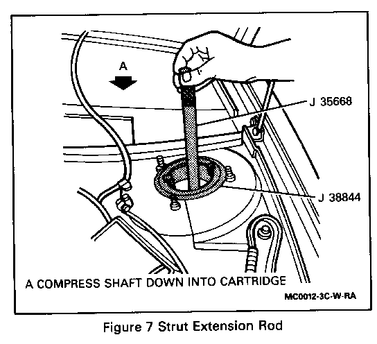
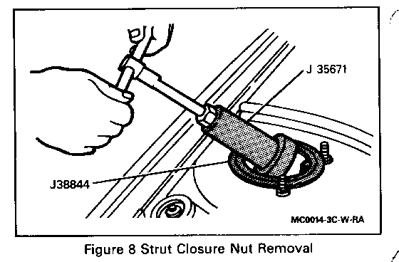
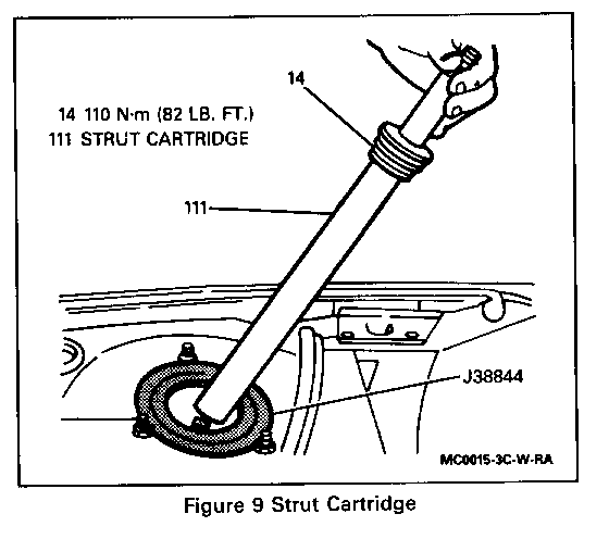
1. Scribe strut cover to body to assure proper camber adjustment. 2. Strut mount cover plate (2) by removing three cover plate nuts (1), (Figure 1). o Convertible-strut tower brace. 3. Strut shaft nut (4) using No. 50 Torx bit and J 35669, (Figure 2). 4. Strut mount bushing (5) by prying with suitable tool, (Figure 3). o Use J35668 to apply pressure on strut shaft (13) as necessary to relieve bushing (compression) side load. 5. Jounce bumper (7) by attaching J 35668 to strut shaft and pulling out jounce bumper. (Figure 4). 6. Install J 38844, (Figure 5). o Use information shown on label of J 38844 to install in correct position. (Figure 6). 7. Compress strut shaft (I 3) down into cartridge, (Figure 7). 8. Strut cartridge closure nut (1 4) by unscrewing closure nut using J 35671, (Figure 8). 9. Strut cartridge (I 1 1), (Figure 9). 10. Oil from strut tube using suction device.
Install or Connect:
1. Self-contained replacement cartridge (111). 2. Strut cartridge closure nut (14) using J35671 tighten to 110 N.m (82 lbs.ft.). 3. Install J 35668. 4. Remove J 38844. 5. Jounce bumper (7). 6. Raise strut shaft and remove J 35668. 7. Strut mount bushing (5). o Use a soap solution to lubricate bushing for ease of installation. o If necessary, install J 35668 after bushing is partially installed and position strut shaft as required to assist in bushing installation. 8. Strut shaft nut (4) using No. 50 Torx bit and J 35669 tighten to 98 N.m (72 lbs. ft.). 9. Strut mount cover and nuts, align scribe marks and tighten to 24 N.m (18 lbs. ft.) o Convertible-strut tower brace.
General Motors bulletins are intended for use by professional technicians, not a "do-it-yourselfer". They are written to inform those technicians of conditions that may occur on some vehicles, or to provide information that could assist in the proper service of a vehicle. Properly trained technicians have the equipment, tools, safety instructions and know-how to do a job properly and safely. If a condition is described, do not assume that the bulletin applies to your vehicle, or that your vehicle will have that condition. See a General Motors dealer servicing your brand of General Motors vehicle for information on whether your vehicle may benefit from the information.
