POWER SUNROOF (OPT CF5) PONTIAC 19&27 BODY STYLES

VEHICLES AFFECTED: Pontiac 2AF/AC 19 and 27 Styles
A power sunroof (Option CF5) is available on coupes and sedans and is electrically operated from a switch located at the center of the roof. When the switch is depressed rearward, the glass panel slides into the storage space between the roof and the headlining. Depressing the switch forward will cause the glass panel to move to the closed position. If the switch is pressed forward again while the glass is in the closed position, the rear edge of the glass will raise to the vent position. To close the glass from the vent position, push the switch rearward. The switch must be depressed for each separate operation.
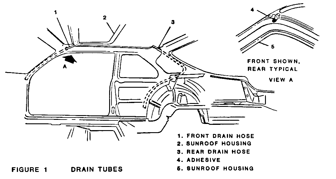
The sliding panel is designed to have a controlled water entry at the seal. Adequate drainage is provided by four drain hoses, one at each corner of the sunroof housing (Fig. 1). A properly adjusted glass panel should result in a snug fit between the seal and the roof. The fit can be checked by using a 0.10 feeler gauge inserted between the roof and the seal at the front and rear of the glass panel. Maintenance of this minimal gap is essential to assure that more water does not enter the vehicle than the sunroof drains can handle. Also, objectionable windnoise could result if gap clearances are exceeded. All glass panel to roof adjustments are made by either adjusting the height of the glass, or adjusting the crown of the roof.
WATER DRAINAGE SYSTEM
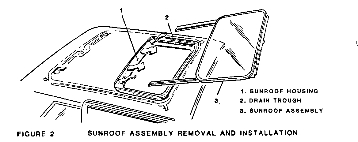
A drain trough (Fig. 2) encircles the sliding panel and leads to a drain hose located at each corner of the housing. The two front drain hoses are routed down the windshield pillars and out the center of the pillar near the upper door hinge. The two rear drain hoses are routed down the rear pillars to the inside of the dog leg. They are accessible by removal of the pressure relief valve located in the rear door body lock pillar.
If a wet headliner or other water leak complaints are encountered, prior to performing any adjustments, first verify that the drainage system is not plugged or restricted. Use a pint size container and pour water into drain trough (Fig. 2). Check that water drains from all four hoses. If water flow is restricted, use compressed air to blow out any material plugging the drain system. Retest system again.
If water drips from the headliner above the door or quarter window, lower headliner as required and check to see if drain tube(s) are connected. To assess situation, partial access may be had by removing lace around sunroof opening and lowering headliner. If necessary, re-cement hose in place using weatherstrip adhesive such as 3M 08011 or equivalent.
GLASS HEIGHT AND OPENING FIT ADJUSTMENT
- Adjust
1. Open glass panel.
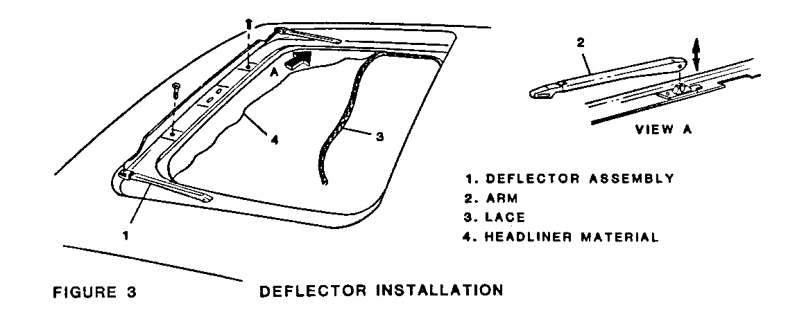
2. Unsnap deflector arms from side tracks (Fig. 3, View A). Remove two screws securing wind deflector assembly to forward edge of track assembly and lift out deflector assembly.
3. Close glass and slide sunshade fully rearward.
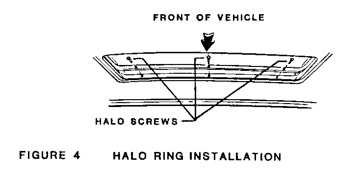
4. Remove three screws from front edge of halo (Fig. 4) and slide halo fully rearward.
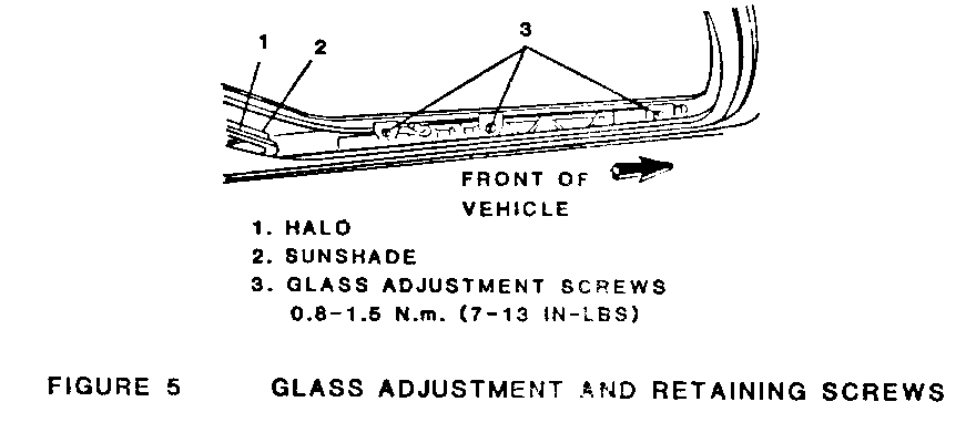
5. Loosen three attaching screws on each side of glass (Fig. 5) and adjust glass height so that front of glass is .79mm (1/32") below flush with roof and rear of glass is .79mm (1/32") above finish.
6. The six glass attaching screws also allow for minimal forward or rearward glass adjustment to obtain the correct 2.54mm (0.10") gap between the seal and the roof.
7. Reassemble halo to glass assembly and reinstall deflector.
ROOF REAR CROWN ADJUSTMENT
Correct roof rear contour is essential for proper sealing action between the roof opening and the seal. Overcrowning or undercrowning can cause windnoise or water leak conditions. Before attempting this adjustment, the crown of the roof should be carefully assessed to dete mine the roof to glass seal relationship. Open the glass panel slightly and compare the contour of the roof and glass panels. If the roof panel appears flattened in the center and/or the glass scuffs the underside of the roof panel, remove the sliding panel from the vehicle and re-arch the roof panel.
CAUTION:
Excessive rework could distort the roof panel and require costly metal finishing repair. This procedure should be used only as a last resort and adjustments should be done in small increments.
If the roof panel has too much arch or is overcrowned and requires some downward deflection, be aware that care should be taken not to lower the crown so much that it contacts and scratches the glass. Protect the glass until adjustment is complete.
DIAGNOSIS
Refer to Trouble Diagnosis Table for information on diagnosis of system.
TROUBLE DIAGNOSIS TABLE
CONDITION APPARENT CAUSE CORRECTION --------- --------------- ---------- - Water leaks Glass panel not properly Align glass panel aligned or fitted to roof.
Glass panel not fully Adjust to specifications. closing. Excessive gap .25mm (+.010").
Drain tubes not Connect properly and/or properly connected fix or replace drain and/or blocked. tubes as required.
Glass assembly seal not Install seal properly properly in place and/or and/or attach correctly. attached securely. ------------------------------------------------------------------------------ - Windnoise Glass panel not properly Align and/or fit glass fitted or aligned. panel to specifications.
Glass panel not fully Adjust to specifications. closing. Excessive gap .25mm (+.010")
Glass assembly seal not Install seal properly properly in place and/or and/or attach correctly. attached securely. ------------------------------------------------------------------------------ - Moon Roof does Glass panel not properly Align and/or fit glass not function aligned or fitted to roof. panel to specifications. and/or perform properly Glass assembly seal not Install seal properly properly in place and/or and/or attach correctly. attached securely.
Obstructions or foreign Remove obstructions or objects in tracks or foreign objects as troughs. required.
Rear guide pin not Engage rear guide pin properly engaged in cam properly. Add slot of lifter assembly. retaining clip as required.
Rear lifter assemblies Properly connect lifter not properly connected assemblies to glass to glass module. module.
Lifter plastic slides Install lifter slides not properly installed as required. in track slots.
Adequate voltage not Check voltage and correct being supplied to ) the if voltage not adequate. motor (12.6 volts.
Tracks not securely Attach track securely to attached to housing. housing.
Rear guide cables not Synchronize cables and properly synchronized. motor.
Rear drive cable or Replace or service as guide broken. required.
Sunshade not properly Check and install installed. sunshade properly as required.
Amperage range for Check for proper amperage glass running not and correct if required. adequate (3-5 Amps). ------------------------------------------------------------------------------ - Noisy Operation Glass panel not fitted Fit glass panel. properly to housing.
Glass assembly seal not Properly fit and/or properly in place secure glass assembly and/or secured. seal.
Rear guide pins not Engage rear guide pins properly engaged in cam properly and add slot of lifter assembly. retaining clip as required.
Rear lifter assemblies Properly attach lifter not properly attached assembly to glass to glass module. module.
Lifter plastic slides Properly install or not properly installed service as required. in track slots.
Track assembly not Secure track assembly properly secured to to housing. housing.
Rear drive cables not Synchronize cables properly synchronized. and motor.
Sunshade not installed Check and install properly. sunshade properly as required.
Amperage range for Check for proper glass running not amperage and correct adequate. if required. ------------------------------------------------------------------------------ - Rattles Glass panel not Align glass panel to properly aligned or specification. fitted to roof.
Glass panel not fully Adjust to specification. closing.
Drain tubes not Connect properly and/or properly connected fix to replace drain and/or blocked. tubes as required.
Glass assembly seals Install seals properly not properly in place and/or attach correctly. and/or not attached securely.
Obstructions or foreign Remove obstructions or objects in tracks or foreign objects as troughs. required.
Rear guide pin not Engage rear guide pin properly engaged in properly. Add cam slot of lifter retaining clip as assembly. required.
Rear lifter assemblies Properly connect lifter not properly connected assemblies to glass to glass module. module.
Lifter plastic slides Install lifter slide not properly installed in track slots.
Tracks not attached to Attach securely to housing securely. housing.
Sunshade not installed Check and install properly. sunshade properly as required.
Sunshade magnets rattle. Replace sunshade magnets as required. ------------------------------------------------------------------------------ - Glass Broken or Glass panel not fitted or Align or fit as Scratched aligned properly. required.
Obstructions or foreign Remove foreign objects objects in tracks or and/or obstructions as troughs. required.
Clearance to underside Adjust clearance as of roof panel and required to obtain reinforcement ring not adequate clearance. adequate.
MOTOR
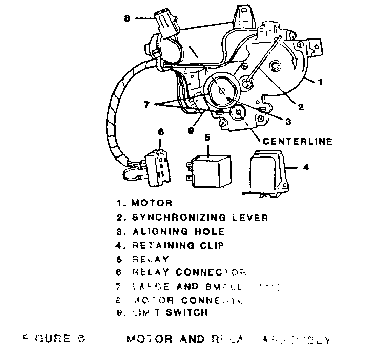
Any time the sunroof motor is removed from the vehicle it must be checked for synchronization before it is reinstalled. The motor is synchronized when the hole in the large cam is aligned with a centerline drawn through the shafts of the large and small cams (Fig. 6). To synchronize the motor, proceed as follows:
- Remove or Disconnect
1. Sunvisors
2. Lace from front of sunroof opening (Fig. 3) and headlining material as required. Release hook and loop retainer strips securing underside of headlining toheader and partially lower headlining.
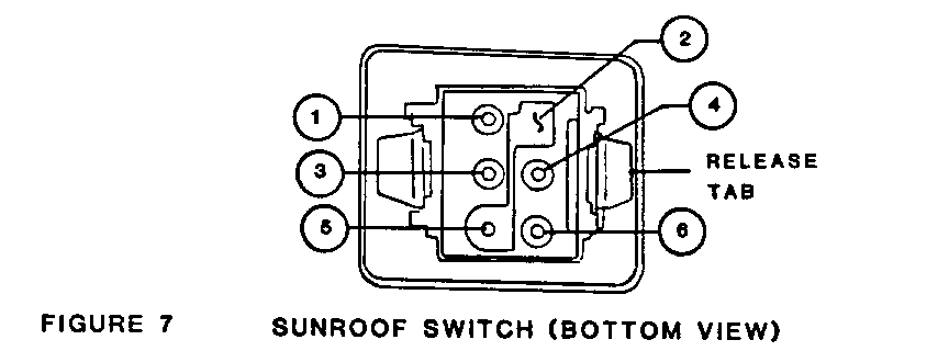
3. Depress release tabs on side of switch body (Fig. 7) and pull switch downward.
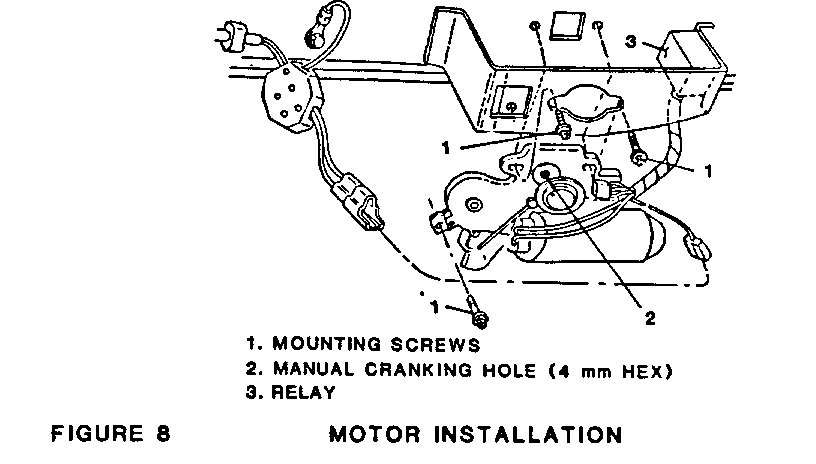
4. Screws securing motor to track assembly and housing roof bracket (Fig. 8) and partially withdraw motor. If motor is only to be synchronized, proceed to Adjust procedures.
5. Pull relay from housing roof bracket, disconnect motor connector (8, Fig. 6), and complete removal of motor.
- Install or Connect
Install motor reverse of removal procedure. Screws securing motor must be aligned in order to thread.
- Adjust
1. Release gear synchronizing lever (2, Fig. 6) from notch on motor casting and rotate lever in direction of arrow on motor casting.
2. Manually rotate small cam using a 4 mm hex wrench (2, Fig. 8) until hole in large cam (3, Fig. 6) is aligned with centerline drawn through shafts of the large and small cams.
3. Return synchronizing lever to notched position.
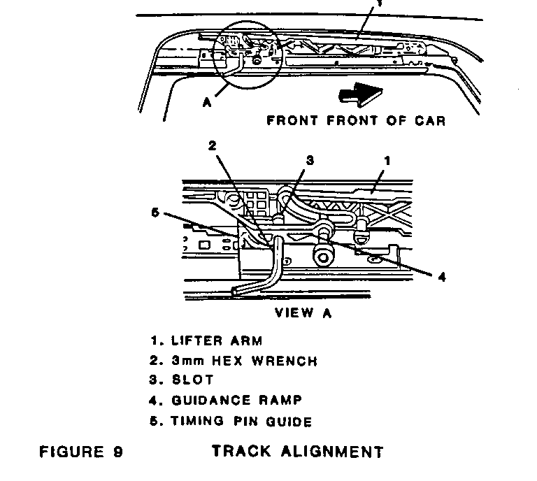
NOTICE: To fully synchronize the system, the lifter arms (1, Fig. 9) and the guidance ramps (4) must also be aligned as shown in Fig. 9. Reference Lifter Arm Install or Connect procedure. Both the motor and the track assembly must be synchronized for proper system operation.
SWITCH AND RELAY
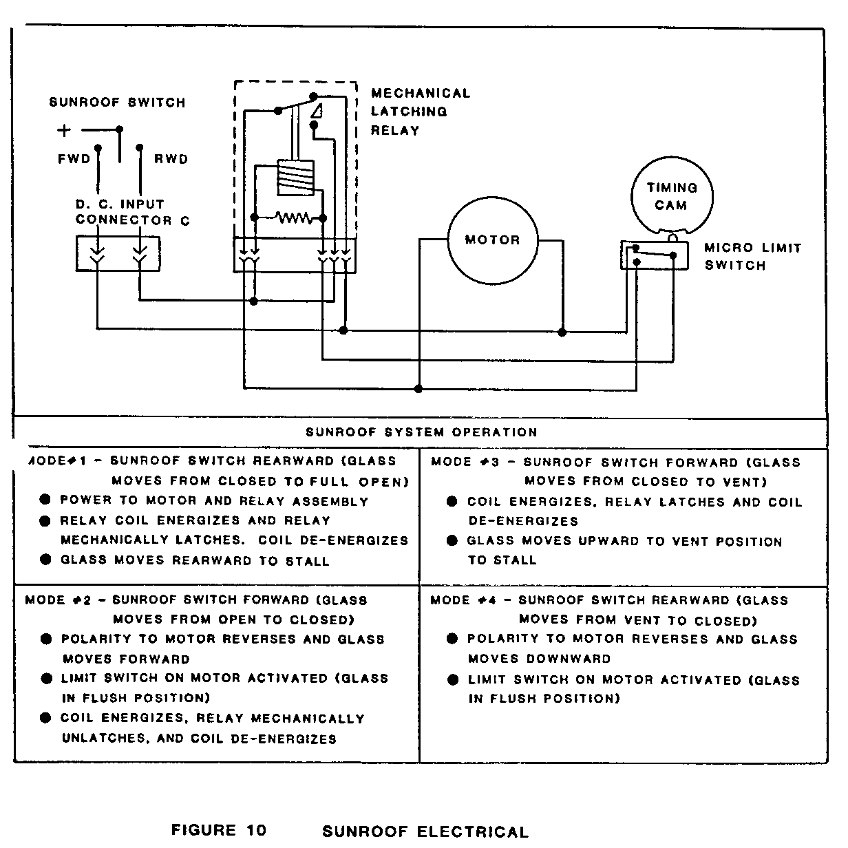
A double acting lever switch is located on the roof panel and controls the forward, rearward and vent positioning of the glass panel. The relay slides into a retainer clip which in turn snaps into the housing roof bracket. Electrical switch and relay relationship to the system circuit is shown in Fig. 10. The switch and relay may be removed and checked for correct operation as follows:
- Remove and Disconnect
1. Partially remove lace (3, Fig. 3) from sunroof opening. Lower headlining along front of opening and gain access to switch body and/or relay. Release hook and loop retainer strips securing underside of headlining to header.
2. Depress release tabs (Fig. 7) on side of switch body and pull switch downward.
3. Separate switch from connector.
4. Remove relay by pulling rearward and separating from connector (Fig. 6).
- Inspect
1. Using a battery powered test lamp or an ohmmeter, and with the switch in normal or neutral position (nondepressed), there should be continuity between terminals 1 and 3, 2 and 5 and 6 (Fig. 7).
2. Depressing the switch lever rearward should establish continuity between terminals 2, 4 and 5, and 1 and 3. Terminal 6 should be disconnected from any other terminal.
3. Depressing the switch lever forward should establish continuity between terminals 2, 3 and 5, 4 and 6. Terminal 1 should be disconnected from any other terminal.
- Install or Connect
Install switch reverse of removal procedure.
GLASS PANEL AND SUNSHADE
- Remove or Disconnect
1. Slide sunshade fully rearward.
2. Three screws securing halo to glass panel (Fig. 4) and slide fully rearward to expose screws, three each side (3, Fig. 5) retaining glass to lifter arm (1, Fig. 9).
3. Screws retaining glass to lifter arm and remove glass panel. To help gain access to screws, glass may be partially opened to reach front screws, then raised to vent position to reach rear screws.
4. Slide halo and sunshade forward, halfway across sunroof opening.
5. Lift halo to clear sunshade, then push halo fully rearward (Fig. 5).
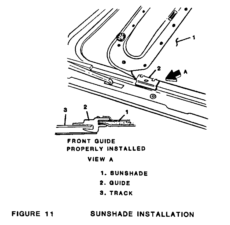
6. Push sunshade fully forward, deflect center of sunshade upward to disengage guides (2, Fig. 11) from track and lift out sunshade.
- Install or Connect
1. Sunshade -- position so that both guides on one side and guide on opposite rear corner are properly located in track slot (Fig. 11, View A). Flex sunshade upward in center and insert remaining guide. Incorrect location of guides is easily accomplished.
2. Slide halo forward of sunshade, then slide sunshade and halo fully rearward.
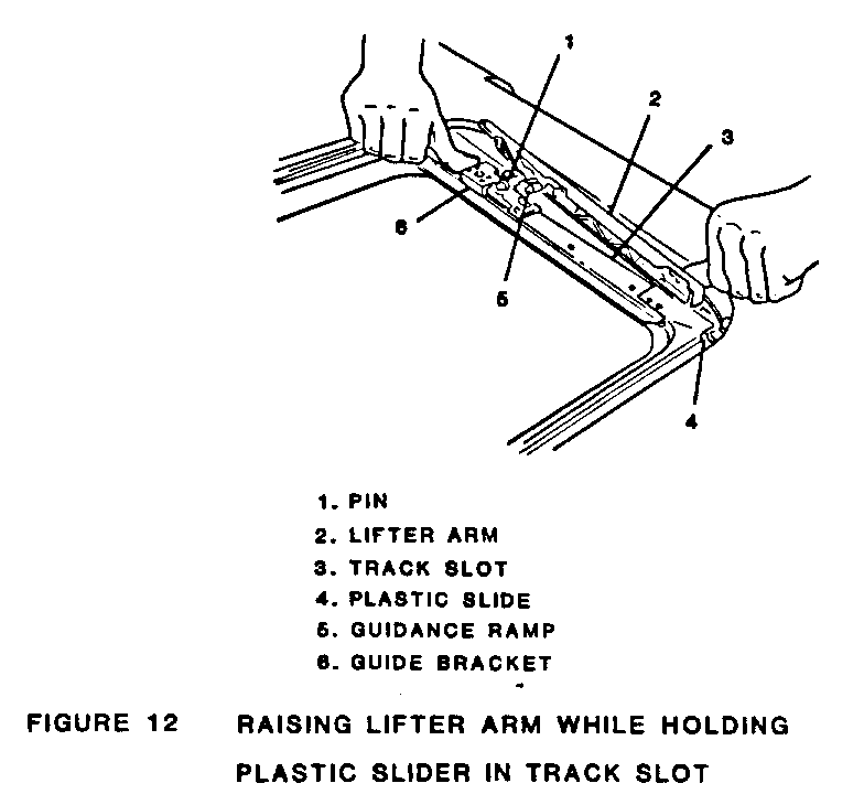
3. Glass -- align height as previously described. Take care not to disengage the plastic slide (4, Fig. 12) on forward portion of lifter arms from track slot. If plastic slide disengages from track slot, it may be reinserted by placing a 2.5 mm hex wrench next to the track and under the plastic slide. Using the wrench as a platform, depress the plastic slide and fit it back into track slot.
4. Complete installation reverse of removal procedure.
GLASS WEATHERSTRIP
- Remove or Disconnect
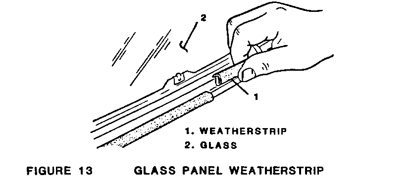
1. Glass panel as previously described.
2. Weatherstrip by pulling it away from channel at rim of glass (Fig. 13).
- Install or Connect
Install weatherstrip reverse of removal procedure. Adjust glass height as required to achieve good sealing action.
WIND DEFLECTOR ASSEMBLY
- Remove or Disconnect
1. Open glass panel and unsnap deflector arms from slide tracks (Fig. 3, View A).
2. Remove two screws securing wind deflector to forward edge of track assembly and lift out deflector assembly.
- Install or Connect
Install wind deflector reverse of removal procedure.
LIFTER ARM
- Remove or Disconnect
1. Glass panel
2. Motor
3. Raise lifter arm (2, Fig. 12) to vent position by holding plastic slide in track slot and pushing guide bracket (6) forward to stop.
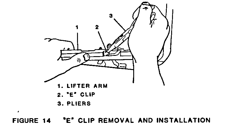
4. Hold lifter arm and remove "E" clips with needle nose pliers (Fig. 14).
5. Pull lifter arm off guidance ramp retaining pin and slide out of track.
- Install or Connect
Install reverse of removal procedure and synchronize both cables by aligning lifter a ms and guidance ramp holes with track slots. Install 4 mm hex wrench into slots (Fig. 9) and be sure hex wrench bottoms out against slot in lifter arms. Make sure lifter arm is fully rearward.
SUNROOF ASSEMBLY, HALO, AND CABLE ASSEMBLY
- Remove or Disconnect
1. Protect painted surfaces adjacent to roof opening.
2. Open glass panel.
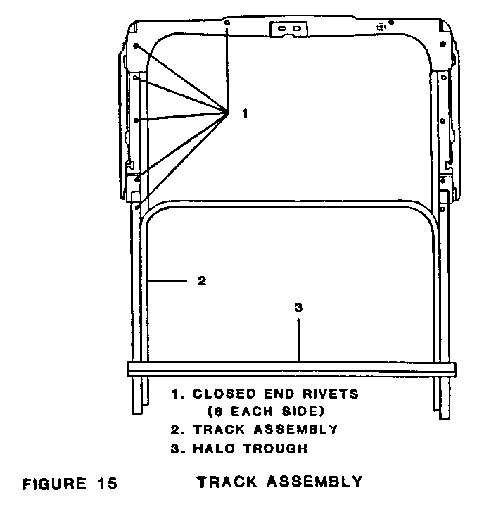
3. Using 3/8" drill stop, drill out 12 rivets securing track assembly to sunroof housing (Fig. 15).
4. Close glass panel.
5. Sunvisors
6. Pull lace (3, Fig. 3) from around sunroof opening, partially withdraw headliner material (4) tucked into slot around opening.
7. Depress release tabs on side of switch body (Fig. 7) and pull switch downward.
8. Screws securing motor to track assembly and housing roof bracket (1, Fig. 8) and partially lower motor.
9. Lift and slide entire sunroof assembly from vehicle (Fig. 2). Make certain halo trough (3, Fig. 15) located at rear of halo clears opening.
- Disassemble
1. Glass panel and sunshade
2. Remove "E" clip from guidance ramp retaining pin (2, Fig. 14), disengage lifter arm from guidance ramp and withdraw plastic slide on forward portion of lifter arm from track slot.
3. If only halo is to be removed, carefully bend one track of halo inward and pull tab out of channel. Disengage opposite tab and lift off halo.
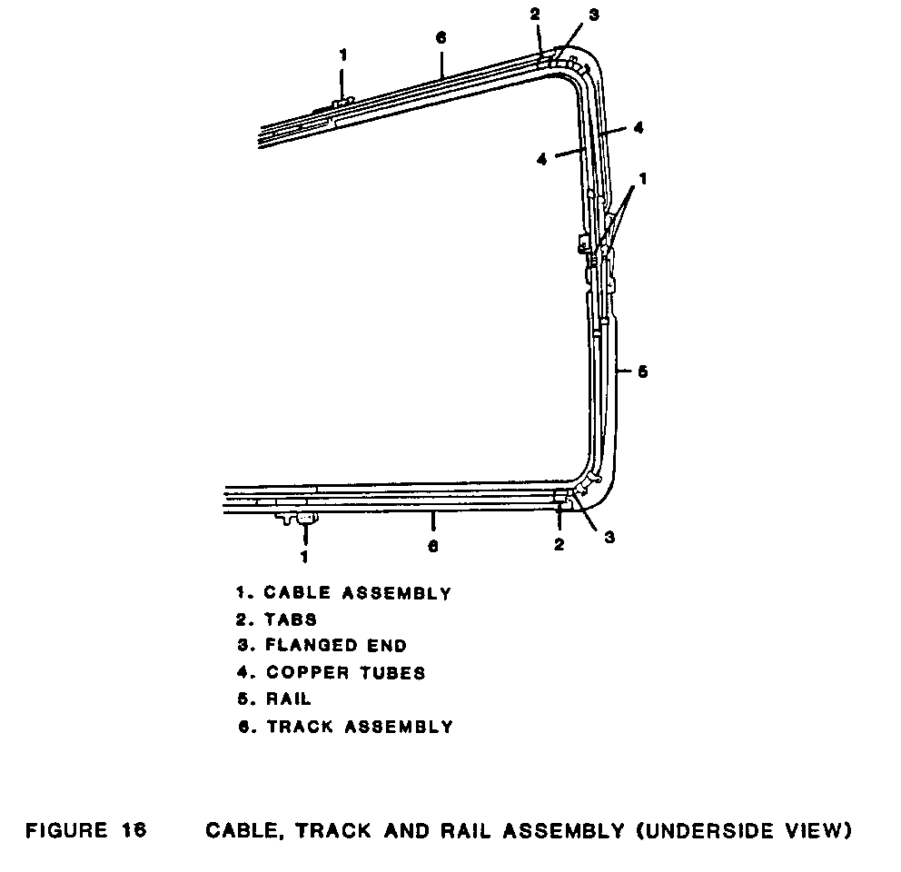
4. Slide cable assembly (1, Fig. 16) out of rear end of track.
- Assemble
1. Slide cable assembly into track.
2. Install halo
3. Lifter arms, sunshade and glass panel
- Install or Connect
Install sunroof assembly reverse of removal procedure and synchronize motor and track assembly. Adjust track height as required.
General Motors bulletins are intended for use by professional technicians, not a "do-it-yourselfer". They are written to inform those technicians of conditions that may occur on some vehicles, or to provide information that could assist in the proper service of a vehicle. Properly trained technicians have the equipment, tools, safety instructions and know-how to do a job properly and safely. If a condition is described, do not assume that the bulletin applies to your vehicle, or that your vehicle will have that condition. See a General Motors dealer servicing your brand of General Motors vehicle for information on whether your vehicle may benefit from the information.
