GM Service Manual Online
For 1990-2009 cars only

Chime Sounds When Key is Removed from Ignition (Inspect/Replace Lock Cylinder)

Subject:Chime Sounds When Key is Removed from Ignition, Intermittent Operation of Power Door Locks, Keyless Entry, Steering Column Lock or Memory Seats (Inspect/Replace Lock Cylinder Actuator or Lock Cylinder Assembly)

Models:1997-99 Chevrolet Corvette, Malibu
1997-99 Oldsmobile Cutlass
1998-99 Oldsmobile Intrigue
1999 Oldsmobile Alero
1999 Pontiac Grand Am


This Bulletin is being revised to add additional symptoms and conditions. Please discard Corporate Bulletin Number 83-83-20 (Section 8 - Chassis/Body Electrical)


Condition

Some customers may comment that the key warning chime continues to sound after the ignition key has been removed from the ignition lock cylinder. They may also comment that the automatic power door locks will not lock the doors when the key is removed from the ignition lock cylinder and the warning chime is sounding.

On Corvette models, some customers may comment that there is an intermittent operation of the passive keyless entry system, the steering column lock, or the retracting feature of the memory power seat option when exiting the vehicle.

Cause

The actuator, located in the ignition lock cylinder, may be sticking after the key is removed.

Correction

Remove the ignition lock cylinder for the instrument panel using the following procedures. Once removed from the vehicle, use the "Actuator Type Identification" and "Test Procedure" sections later in this bulletin to determine the correct repair procedure.

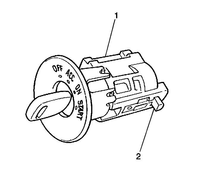
Figure 1


Object Number: 622898  Size: SH
(1)Installed Position of the Ignition Lock Cylinder
(2)Location of the Release Plunger (tab) at the 4 o'clock position

Malibu and Cutlass Models -- Lock Cylinder Removal

Use the following steps to remove the lock cylinder:

    Caution: When you are performing service on or near the SIR components or the SIR wiring, you must disable the SIR system. Refer to Disabling the SIR System. Failure to follow the correct procedure could cause air bag deployment, personal injury, or unnecessary SIR system repairs.

  1. Disable the SIR system. See the SIR sub-section of Restraints in the Service Manual.
  2. Remove the lock cylinder bezel.
  3. Remove the accessory trim plate. See the Instrument Panel & Console sub-section of Body & Accessories in the Service Manual.
  4. Remove the radio. See the Instrument Panel & Console sub-section of Body & Accessories in the Service Manual.
  5. Insert the key into the lock cylinder and turn to the ON position.
  6. Depress and hold the release plunger (tab) on the side of the lock cylinder and pull the lock cylinder from the instrument panel. See Figure 1 for location of the release plunger (tab).
  7. See the "Actuator Type Identification" and "Test Procedure" sections later in this bulletin to determine the correct repair procedure.
Malibu and Cutlass Models -- Lock Cylinder Installation

Use the following steps to install the lock cylinder:

  1. With the key in the lock cylinder and in the ON position, insert the lock cylinder into the instrument panel until the plunger locks in place.
  2. Install the radio. See the Instrument Panel & Console sub-section of Body & Accessories in the Service Manual.
  3. Install the accessory trim plate. See the Instrument Panel & Console sub-section of Body & Accessories in the Service Manual.
  4. Install the lock cylinder bezel.
  5. Enable the SIR system. See the SIR sub-section of Restraints in the Service Manual.
  6. Reprogram the theft deterrent system (only if a new lock cylinder is installed).

Alero and Grand Am Models -- Lock Cylinder Removal

Use the following steps to remove the lock cylinder:

    Caution: When you are performing service on or near the SIR components or the SIR wiring, you must disable the SIR system. Refer to Disabling the SIR System. Failure to follow the correct procedure could cause air bag deployment, personal injury, or unnecessary SIR system repairs.

  1. Disable the SIR system. See the SIR sub-section of Restraints in the Service Manual.
  2. Remove the shift knob/handle (Alero Only).
  3. Remove the console shifter trim plate (Alero Only). See the Instrument Panel & Console sub-section of Body & Accessories in the Service Manual.
  4. Remove the lock cylinder bezel.
  5. Remove the accessory trim plate. See the Instrument Panel & Console sub-section of Body & Accessories in the Service Manual.
  6. Remove the radio. See the Instrument Panel & Console sub-section of Body & Accessories in the Service Manual.
  7. Insert the key into the lock cylinder and turn to the ON position.
  8. Depress and hold the release plunger (tab) on the side of the lock cylinder and pull the lock cylinder from the instrument panel. See Figure 1 for location of the release plunger (tab).
  9. See the "Actuator Type Identification" and "Test Procedure" sections later in this bulletin to determine the correct repair procedure.

Alero and Grand Am Models -- Lock Cylinder Installation

Use the following steps to install the lock cylinder:

  1. With the key in the lock cylinder and in the ON position, insert the lock cylinder into the instrument panel until the plunger locks in place.
  2. Install the radio. See the Instrument Panel & Console sub-section of Body & Accessories in the Service Manual.
  3. Install the accessory trim plate. See the Instrument Panel & Console sub-section of Body & Accessories in the Service Manual.
  4. Install the lock cylinder bezel.
  5. Install the console shifter trim plate (Alero Only). See the Instrument Panel & Console sub-section of Body & Accessories in the Service Manual.
  6. Install the shift knob/handle (Alero Only).
  7. Enable the SIR system. See the SIR sub-section of Restraints in the Service Manual.
  8. Reprogram the theft deterrent system (only if a new lock cylinder is installed).

Intrigue Models -- Lock Cylinder Removal

Use the following steps to remove the lock cylinder:

    Caution: When you are performing service on or near the SIR components or the SIR wiring, you must disable the SIR system. Refer to Disabling the SIR System. Failure to follow the correct procedure could cause air bag deployment, personal injury, or unnecessary SIR system repairs.

  1. Disable the SIR system. See the SIR sub-section of Restraints in the Service Manual.
  2. Remove the left side instrument panel insulator. See the Instrument Panel & Console sub-section of Body & Accessories in the Service Manual.
  3. Remove the console trim plate. See the Instrument Panel & Console sub-section of Body & Accessories in the Service Manual.
  4. Remove the accessory trim plate. See the Instrument Panel & Console sub-section of Body & Accessories in the Service Manual.
  5. Remove the radio. See the Instrument Panel & Console sub-section of Body & Accessories in the Service Manual.
  6. Insert the key into the lock cylinder and turn to the ON position.
  7. Depress and hold the release plunger (tab) on the side of the lock cylinder and pull the lock cylinder from the instrument panel. See Figure 1 for location of the release plunger (tab).
  8. See the "Actuator Type Identification" and "Test Procedure" sections later in this bulletin to determine the correct repair procedure.

Intrigue Models -- Lock Cylinder Installation

Use the following steps to install the lock cylinder:

  1. With the key in the lock cylinder and in the ON position, insert the lock cylinder into the instrument panel until the plunger locks in place.
  2. Install the radio. See the Instrument Panel & Console sub-section of Body & Accessories in the Service Manual.
  3. Install the accessory trim plate. See the Instrument Panel & Console sub-section of Body & Accessories in the Service Manual.
  4. Install the console trim plate. See the Instrument Panel & Console sub-section of Body & Accessories in the Service Manual.
  5. Install the left side instrument panel insulator. See the Instrument Panel & Console sub-section of Body & Accessories in the Service Manual.
  6. Enable the SIR system. See the SIR sub-section of Restraints in the Service Manual.
  7. Reprogram the theft deterrent system (only if a new lock cylinder is installed).

Corvette Models -- Lock Cylinder Removal

Use the following steps to remove the lock cylinder:

    Caution: When you are performing service on or near the SIR components or the SIR wiring, you must disable the SIR system. Refer to Disabling the SIR System. Failure to follow the correct procedure could cause air bag deployment, personal injury, or unnecessary SIR system repairs.

  1. Disable the SIR system. See the SIR sub-section of Restraints in the Service Manual.
  2. Remove the console. See the Instrument Panel & Console sub-section of Body & Accessories in the Service Manual.
  3. Remove the instrument panel accessory trim plate. See the Instrument Panel & Console sub-section of Body & Accessories in the Service Manual.
  4. Disconnect the electrical connector from the lock cylinder.
  5. Insert the key into the lock cylinder and turn to the ON position.
  6. Depress and hold the release plunger (tab) on the side of the lock cylinder and pull the lock cylinder from the instrument panel. See Figure 1 for location of the release plunger (tab).
  7. See the "Actuator Type Identification" and "Test Procedure" sections later in this bulletin to determine the correct repair procedure.

Corvette Models -- Lock Cylinder Installation

Use the following steps to install the lock cylinder:

  1. With the key in the lock cylinder and in the ON position, insert the lock cylinder into the instrument panel until the plunger locks in place.
  2. Connect the electrical connector to the lock cylinder.
  3. Install the instrument panel accessory trim plate. See the Instrument Panel & Console sub-section of Body & Accessories in the Service Manual.
  4. Install the console. See the Instrument Panel & Console sub-section of Body & Accessories in the Service Manual.
  5. Enable the SIR system. See the SIR sub-section of Restraints in the Service Manual.

Figure 2 -- End View of Ignition Lock Cylinder for Actuator Identification


Object Number: 622901  Size: MH
(1)Early Design Actuator in the Lock Cylinder
(2)Side View of the Early Design Actuator When Removed from the Lock Cylinder
(3)New Design Actuator in the Lock Cylinder
(4)Side View of the New Design Actuator When Removed from the Lock Cylinder

Actuator Type Identification

With the key installed, hold the lock cylinder as shown in Figure 2 to determine what type of actuator is being used. FOLLOW THE APPROPRIATE TEST PROCEDURE FOR THE TYPE OF ACTUATOR BEING USED.

Figure 3 -- Lock Cylinder in Vertical Position for Actuator Testing


Object Number: 622902  Size: SH
(1)Actuator in the Up Position with the Key INSTALLED in the Lock Cylinder
(2)Actuator in the Down Position with the Key REMOVED from the Lock Cylinder

Test Procedure

Early Design Actuator:

  1. With the lock cylinder held vertically as shown in Figure 3, remove the key from the lock. When the key is removed, the actuator should drop down in the lock cylinder approximately 4-5 mm (3/16 in). Repeat this step several times.
  2. If the EARLY design actuator in the lock cylinder does NOT drop down, replace the complete lock assembly.
  3. If the EARLY design actuator in the lock cylinder DOES drop down, replace the actuator with the new design actuator P/N 12450483.

To replace the actuator, install the key in the lock and grasp the end of the actuator with a pair of small long nose (needle nose) pliers and pull firmly. With the key still in the lock, install the new actuator by aligning the actuator shaft with the opening in the lock cylinder and pushing the actuator into place. Verify the correct actuator operation by performing Step 1 again.

Important: After installing a new actuator, correct actuator operation must be confirmed.

Test Procedure

New Design Actuator:

  1. With the lock cylinder held vertically as shown in Figure 3, remove the key from the lock. When the key is removed, the actuator should drop down in the lock cylinder approximately 4-5 mm (3/16 in). Repeat this step several times.
  2. If the NEW design actuator in the lock cylinder does NOT drop down, replace the lock cylinder assembly.

Parts Information

Part Number

Description

Application

12450483

Actuator

All Models Listed Above

12458191

Lock Service Package

All, (Except Corvette)

12458190

Lock Service Package

Corvette Only

Parts are currently available from GMSPO.

Warranty Information

For vehicles repaired under warranty, use:

Labor Operation

Description

Models

Labor Time

E7200

Cylinder, Ignition Lock - R&R or Replace

Corvette

0.7 hr

Alero

0.5 hr

Malibu, Cutlass, Grand Am and Intrigue

0.4 hr

Add:

Diagnosis Time (Includes Replacing Actuator)

Authorization Required

0.1 hr

To Code New Lock Cylinder

Authorization Required

0.3 hr

To Reprogram with Passlock System - Except Corvette (Only Required When New Lock Cylinder is Installed)

Authorization Required

0.2 hr