For 1990-2009 cars only
Tools Required
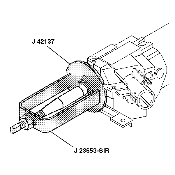
| • | J 42137 Lock Plate Compressor Adapter |
| • | J 23653-SIR Lock Plate Compressor |
- Install the bearing and housing assembly.
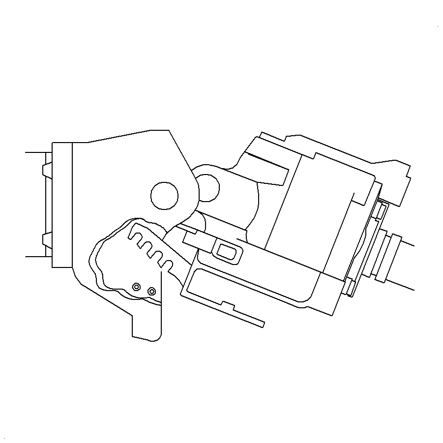
- Pull the tilt arm to lift the steering wheel lock shoes onto the dowel pins in the steering column support assembly to install the bearing and housing assembly.
- Install the tilt spring assembly only. Refer to Tilt Spring - Assemble - Off Vehicle .
- Install the 2 pivot pins. Lubricate the pivot pins with lithium grease.
- Stake the pivot pins in 3 places after installed.
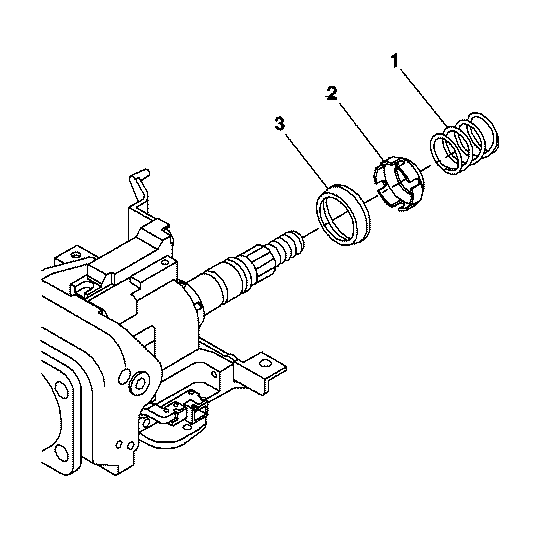
- Install the inner race (3).
- Install the upper bearing inner race seat (2).
- Install the upper bearing spring (1).
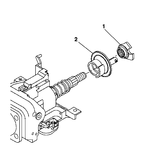
- Install the turn signal cancel cam assembly (2).
- Install the cam orientation plate (1).
- Install the bearing retainer using J 23653-SIR and the J 42137 .
- Install the inflatable restraint steering wheel module coil. Refer to Inflatable Restraint Steering Wheel Module Coil Assemble - Off Vehicle .
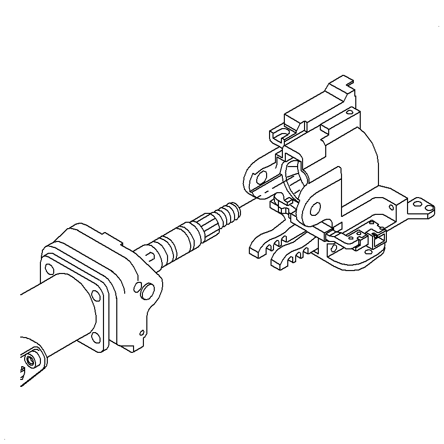
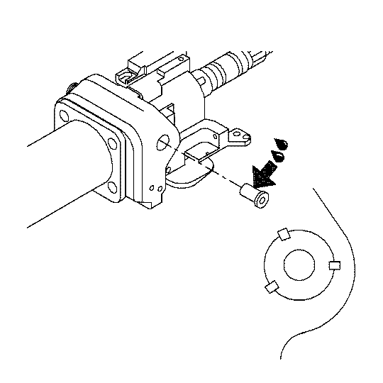
Important: If the steering column support assembly and the pivot pins have been staked three times they must be replaced.
