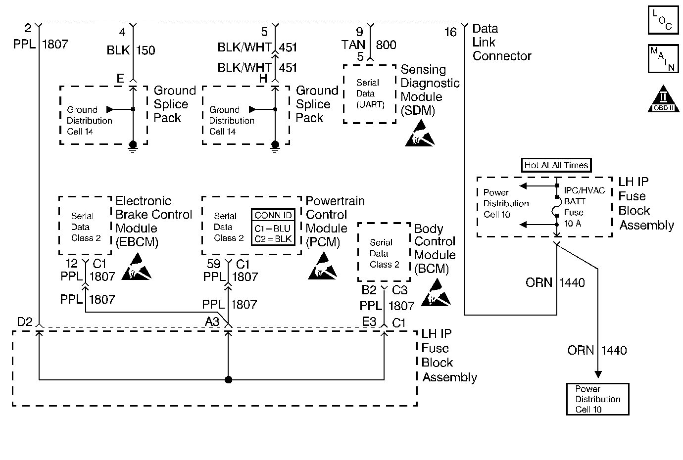
Circuit Description
A Class 2 serial data communications system is used on this vehicle in order to allow various modules to communicate and share information with each other. Each bit of information has one of two lengths: long or short. This allows for the reduction of the vehicle wiring, and for the transmission and reception of multiple signals over a single wire. The messages carried on the Class 2 serial data stream are also prioritized. If two messages attempt to establish communications on the data line at the same time, the message with the higher priority will continue. The message with the lower priority message will wait.
All modules on the Class2 serial data line send out a periodic identifier message. The PCM is listening for the identifier messages from the EBCM and the BCM as well as an echo of the PCM identifier message. If a module cannot respond to the PCM, a DTC is stored.
Conditions for Setting the DTC
The PCM does not receive the identifier message from the EBCM.
Action Taken When the DTC Sets
| • | The PCM will record operating conditions at the time the diagnostic fails. This information will store in the Freeze Frame and Failure Records buffers. |
| • | A history DTC stores. |
Conditions for Clearing the MIL/DTC
| • | A history DTC will clear after 40 consecutive warm up cycles without a fault. |
| • | A scan tool can clear the DTCs. |
Diagnostic Aids
Attempting to start the vehicle by bypassing the Passlock ll system or by substituting parts without performing the password learn procedure may set a DTC P1631 and a P1632.
If no password is received, a DTC U1064 and P1632 may be set.
An intermittent may be caused by the following conditions:
| • | Poor electrical connection |
| • | Rubbed through wire insulation |
| • | Broken inside the insulation |
Thoroughly check any suspected circuitry for the following items:
| • | Backed out terminals or improper mating |
| • | Broken locks |
| • | Improperly formed or damaged terminals |
| • | Poor terminal to wiring connections |
| • | Physical damage to the wiring harness |
| • | Corrosion |
Test Description
Number(s) below refer to the step number(s) on the Diagnostic Table.
-
The Powertrain OBD System Check prompts the technician to complete some basic checks and store the freeze frame and failure records data on the scan tool if applicable. This creates an electronic copy of the data taken when the malfunction occurred. The information is then stored in the scan tool for later reference.
-
A scan tool that cannot display PCM data indicates that a short, or open may exist on the serial data circuit. Refer to Data Link Connector Diagnosis for further diagnosis.
-
An intermittent short on the BCM serial data circuit could cause this DTC to set. When the malfunction is present, the scan tool will lose communication with the PCM. Check for chaffed wiring or a malfunctioning BCM module.
-
The DTC is intermittent when a scan tool can communicate with the PCM. DTCs with other modules may lead to a possible cause of the intermittent problem.
-
If no malfunctions have been found at this point and no additional DTCs were set, refer to Diagnostic Aids for additional checks and information.
Step | Action | Value(s) | Yes | No |
|---|---|---|---|---|
Was the Powertrain On-Board Diagnostic (OBD) System Check performed? | -- | |||
Install a scan tool. Can the scan tool display data from the PCM? | -- | |||
3 | Check for an intermittent, short, or open connection on the serial data circuit to the EBCM and repair as necessary. Refer to Wiring Repairs in Wiring Systems. Was a repair necessary? | -- | ||
4 | Check for an intermittent, short, or open connection on the serial data circuit to the BCM and repair as necessary. ry. Refer to Wiring Repairs in Wiring Systems. Was a repair necessary? | -- | ||
Check for DTCs or communication with the other modules and make any necessary repairs. Is the action complete? | -- | -- | ||
6 |
Does the scan tool indicate that this diagnostic ran and passed? | -- | ||
Check if any additional DTCs are set. Are any DTCs displayed that have not been diagnosed? | -- | Go to the applicable DTC table | System OK |
